Typ Engineering Drawing
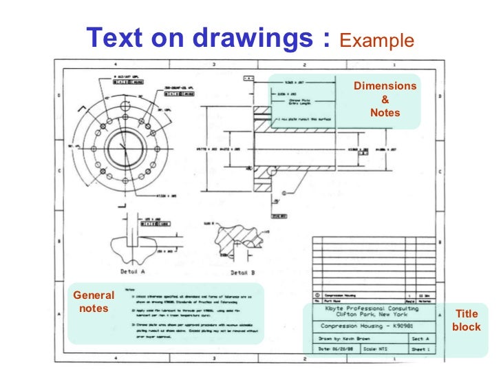
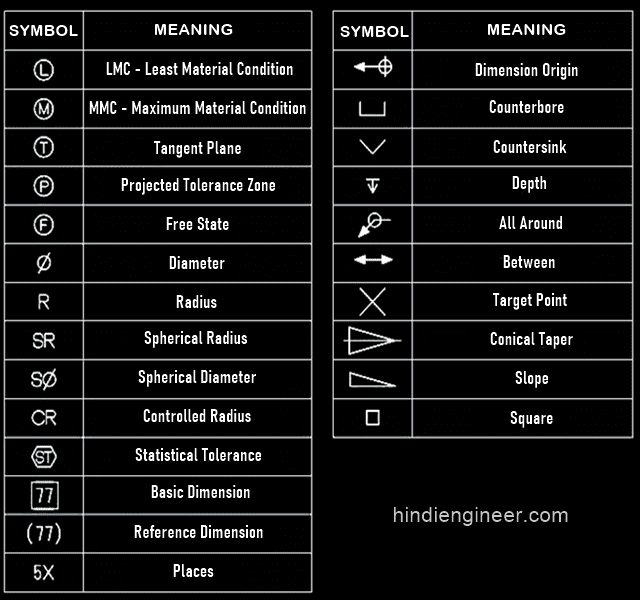
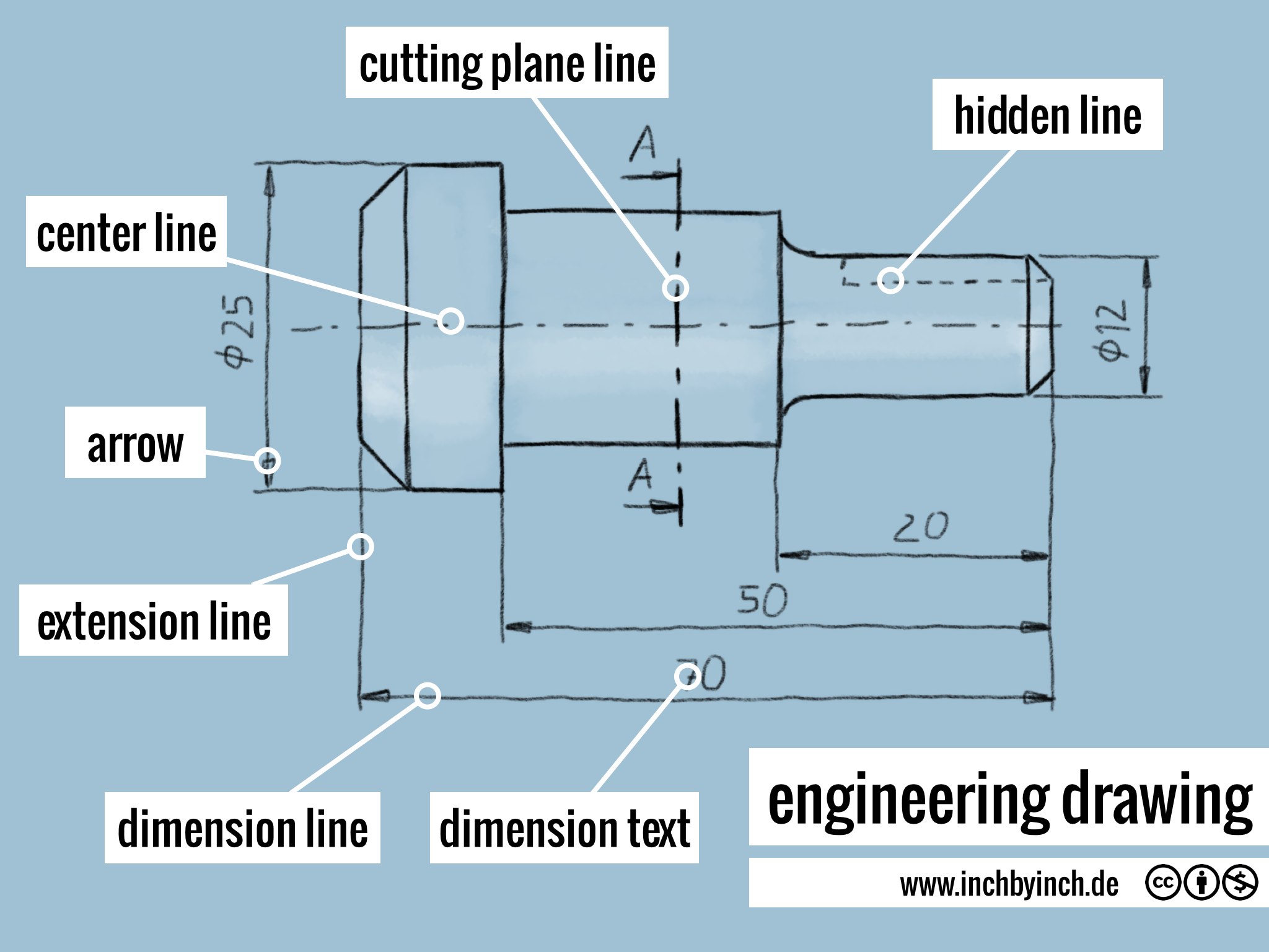
Typ Engineering Drawing - Web typical divided roadway section final layer thicknesses to be determined by the engineers pavement design calculations. Source aws a2.4:2007, section 5.11.3. Web basic types of symbols used in engineering drawings are countersink, counterbore, spotface, depth, radius, and diameter. Engineering standards manual 3 approved by: The typ callout was often used in wall sections to reference typical or common elements of a section. This standard defines the types of engineering drawings most frequently used to establish engineering requirements. The purpose is to convey all the information necessary for manufacturing a product or a part. Where a typical condition is noted, it should be understood that similar conditions are the same unless specifically detailed or noted otherwise. The seal may be ink stamped, embossed, or a digital image, and placed partially overlapping — but not obscuring — your signature. The exception is that typ is an accepted standard for multiple identical weld symbols; Final layer thicknesses to be determined by the engineers pavement design calculations. It also provides a brief introduction to gd&t (geometric dimensioning and tolerancing). In other words, it means that the other 7 holes are that size also.'. Web basic types of symbols used in engineering drawings are countersink, counterbore, spotface, depth, radius, and diameter. Web an engineering drawing is. Definition of typ (typical) in construction. In many instances there are details on the documents that will occur at several different locations, or in several different situations on the construction project. The designation typ means typical on construction documents. Web view city engineering documents and resources related to engineering standards, wastewater details and flood plain certificates. This is identical to. Get the most popular typ abbreviation related to engineering. In other words, it means that the other 7 holes are that size also.'. Web typical divided roadway section final layer thicknesses to be determined by the engineers pavement design calculations. The seal may be ink stamped, embossed, or a digital image, and placed partially overlapping — but not obscuring —. This is often used when there are similar features, and to avoid unnecessary dimensioning by the draftsperson. It describes typical applications and minimum content requirements. A typical dimension callout will occasionally be followed by a 2x, 5x or similar, to specify the quantity of features which are tolerance the same. Engineering drawings use standardised language and symbols. Ref on drawings. Here are more commonly used engineering drawing symbols and design elements as below. In other words, it means that the other 7 holes are that size also.'. Source aws a2.4:2007, section 5.11.3. The purpose is to convey all the information necessary for manufacturing a product or a part. A common use is to specify the geometry necessary for the construction. For example, if the drawing shows 8 holes on a bolt circle, and just one is dimensioned, with typ or (typ) following the dimension label, it means that that hole is typical of all 8 holes; A typical dimension callout will occasionally be followed by a 2x, 5x or similar, to specify the quantity of features which are tolerance the. Drawings for specialized engineering disciplines (e.g., marine, civil, construction, optics, etc.) are not included in this standard. Web engineering documents can be hand signed with a pen, dated, and sealed by the professional engineer in responsible charge. Its proper use can greatly enhance the clarity and efficiency of construction drawings, leading to smoother project execution. Web the video below covers. The seal may be ink stamped, embossed, or a digital image, and placed partially overlapping — but not obscuring — your signature. 2’ level sod seed 2’ level sod roadway.dgn roadway n.t.s. Engineering standards manual 3 approved by: Web engineering drawing abbreviations and symbols are used to communicate and detail the characteristics of an engineering drawing. Web engineering documents can. Here are more commonly used engineering drawing symbols and design elements as below. For additional clarification, please see below. It also provides a brief introduction to gd&t (geometric dimensioning and tolerancing). In mechanical engineering, you often see this callout on hole dimension and the like. We will treat “sketching” and “drawing” as one. Web the duplication of identical welding symbols on a drawing may be avoided by designating a single welding symbol as “typical” (abbreviated as “typ”) and pointing the arrow to the representative joint. Engineering drawings use standardised language and symbols. This standard defines the types of engineering drawings most frequently used to establish engineering requirements. Web the video below covers the. Its proper use can greatly enhance the clarity and efficiency of construction drawings, leading to smoother project execution. Web the typ statement was and perhaps still is an architecture standard and not a mechanical standard. Final layer thicknesses to be determined by the engineers pavement design calculations. It also provides a brief introduction to gd&t (geometric dimensioning and tolerancing). Web engineering documents can be hand signed with a pen, dated, and sealed by the professional engineer in responsible charge. Engineering standards manual 3 approved by: Web typical divided roadway section final layer thicknesses to be determined by the engineers pavement design calculations. This is often used when there are similar features, and to avoid unnecessary dimensioning by the draftsperson. Web an engineering drawing is a type of technical drawing that is used to convey information about an object. The seal may be ink stamped, embossed, or a digital image, and placed partially overlapping — but not obscuring — your signature. Web the video below covers the fundamentals, including the different types of views, first and third angle projection methods, dimensioning, tolerancing, best practices when creating drawings. We will treat “sketching” and “drawing” as one. Web typ means 'other features share the same characteristic. In many instances there are details on the documents that will occur at several different locations, or in several different situations on the construction project. Web the gsfc engineering drawing standards manual is the official source for the requirements and interpretations to be used in the development and presentation of engineering drawings and related documentation for the gsfc. The designation typ means typical on construction documents.
Engineering Drawing Chapter 01 introduction

Engineering drawing symbols TYP שרטוט סימון אוביקט טיפוסי YouTube

how to read engineering drawings engineering drawings YouTube

Different Types of LINES in Engineering Drawing//Classification of

What is TYP in Engineering Drawing. Engineering Drawing me TYP ka kya

Engineering Drawing Symbols List Chart Explain Mechanical Drawing

6 types of engineering drawings

How To Read Mechanical Drawings For Dummies Ronald Adam's Reading

13 Types of Engineering Drawing (Free PDF Download Available

Different Types Of Engineering Drawings
Web What Does Typ Stand For In Engineering?
Engineering Drawings Use Standardised Language And Symbols.
It Describes Typical Applications And Minimum Content Requirements.
This Is Identical To A Feature Which Is Identified As 2X Or 5X.
Related Post: