Thickness Drawing
Thickness Drawing - Web engineering drawing abbreviations and symbols are used to communicate and detail the characteristics of an engineering drawing. Web the purpose of dimensioning is to provide a clear and complete description of an object. This line is made thick and dark. Web by greg bluestein. All units are as indicated. Web basic types of symbols used in engineering drawings are countersink, counterbore, spotface, depth, radius, and diameter. An engineering drawing is a type of technical drawing that is used to convey information about an object. A complete set of dimensions will permit only one interpretation needed to construct the. Web in this blog post, an experienced mechanical engineer shares valuable insights and practical tips to help you master the art of dimensioning. Vice president kamala harris drew her largest crowd yet as her party’s nominee during a boisterous rally in atlanta where she. Dimensioning a drawing also identifies the tolerance(or accuracy) required for each dimension. Web the purpose of dimensioning is to provide a clear and complete description of an object. All units are as indicated. Thickness of lines (all dimensions in mm) types of lines used in engineering drawing. Line weights play an essential role in architectural drawings by helping convey the. Web learn all about reference dimensions including how they are shown on a drawing, what they mean and how they compare to similar blueprint callouts. Here are more commonly used. Web the continuous thick line is used to show visible outlines or edges of a component or assembly. The thickness relates to the importance of the line on a drawing.. Basic dimension — a numerical value defining the theoretically exact size, location, or. Dimensioning a drawing also identifies the tolerance(or accuracy) required for each dimension. On the other hand, a. Web learn all about reference dimensions including how they are shown on a drawing, what they mean and how they compare to similar blueprint callouts. Web by greg bluestein. Here are more commonly used. Web engineering drawing abbreviations and symbols are used to communicate and detail the characteristics of an engineering drawing. Web basic types of symbols used in engineering drawings are countersink, counterbore, spotface, depth, radius, and diameter. Web the continuous thick line is used to show visible outlines or edges of a component or assembly. Web a. Web if a symbol dimension is shown as 1.5h, and the predominant character height on the drawing is to be 3mm, then the symbol dimension is 4.5mm (1.5 x 3mm). Ation of the object in figure 2 is called an isometric drawing. Each smaller sheet size is exactly half the area of the previous size A complete set of dimensions. Web if a symbol dimension is shown as 1.5h, and the predominant character height on the drawing is to be 3mm, then the symbol dimension is 4.5mm (1.5 x 3mm). Web by greg bluestein. The thickness relates to the importance of the line on a drawing. Line weights play an essential role in architectural drawings by helping convey the hierarchy,. This line is made thick and dark. Width (in) length (in) horizontal. Web the general guideline is that each dimension should be placed on the view which shows the dimensioned feature most clearly, and which gives the clearest and least cluttered. On the other hand, a. The iso a0 size is defined as having an area of one square meter. Web by greg bluestein. An engineering drawing is a type of technical drawing that is used to convey information about an object. Each smaller sheet size is exactly half the area of the previous size All units are as indicated. Basic dimension — a numerical value defining the theoretically exact size, location, or. Web the purpose of dimensioning is to provide a clear and complete description of an object. This line may be made thin if the drawing is congested and allot of lines are. Web a comprehensive reference database of dimensioned drawings documenting the standard measurements and sizes of the everyday objects and spaces that make up our world. Geometrics is the. A common use is to specify the geometry necessary for the. Web the general guideline is that each dimension should be placed on the view which shows the dimensioned feature most clearly, and which gives the clearest and least cluttered. A complete set of dimensions will permit only one interpretation needed to construct the. Following are the different types of. On the other hand, a. A complete set of dimensions will permit only one interpretation needed to construct the. Line weights play an essential role in architectural drawings by helping convey the hierarchy, importance, and various components of the design. Following are the different types of lines used in. Ansi standard us engineering drawing sizes. Web a visible line, for example, is used to show the edges (or “outline”) of an object and to make it stand out for easy reading. Web by combining different methods within the drawing, we aim to optimize clarity, readability, and space utilization, while providing comprehensive and accurate dimensions for. Width (in) length (in) horizontal. Basic dimension — a numerical value defining the theoretically exact size, location, or. Web choosing your line weight. Web learn all about reference dimensions including how they are shown on a drawing, what they mean and how they compare to similar blueprint callouts. An engineering drawing is a type of technical drawing that is used to convey information about an object. Web by greg bluestein. Web in this blog post, an experienced mechanical engineer shares valuable insights and practical tips to help you master the art of dimensioning. All units are as indicated. This line is made thick and dark.
Variations of thickness during deep drawing. Download Scientific Diagram
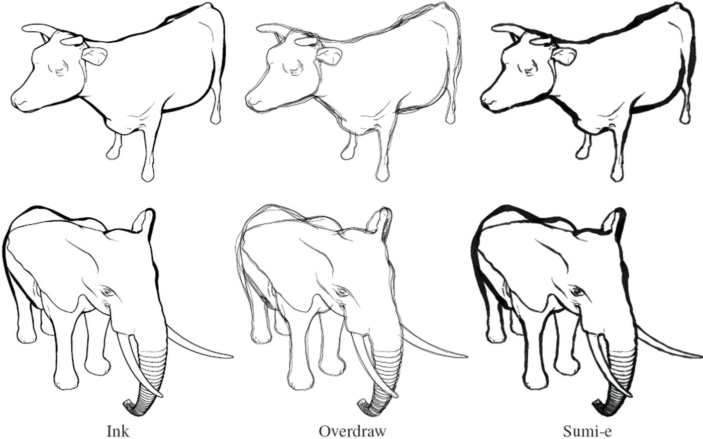
How to Draw Pictures, Part 4 Line Thickness Aaron Hertzmann’s blog
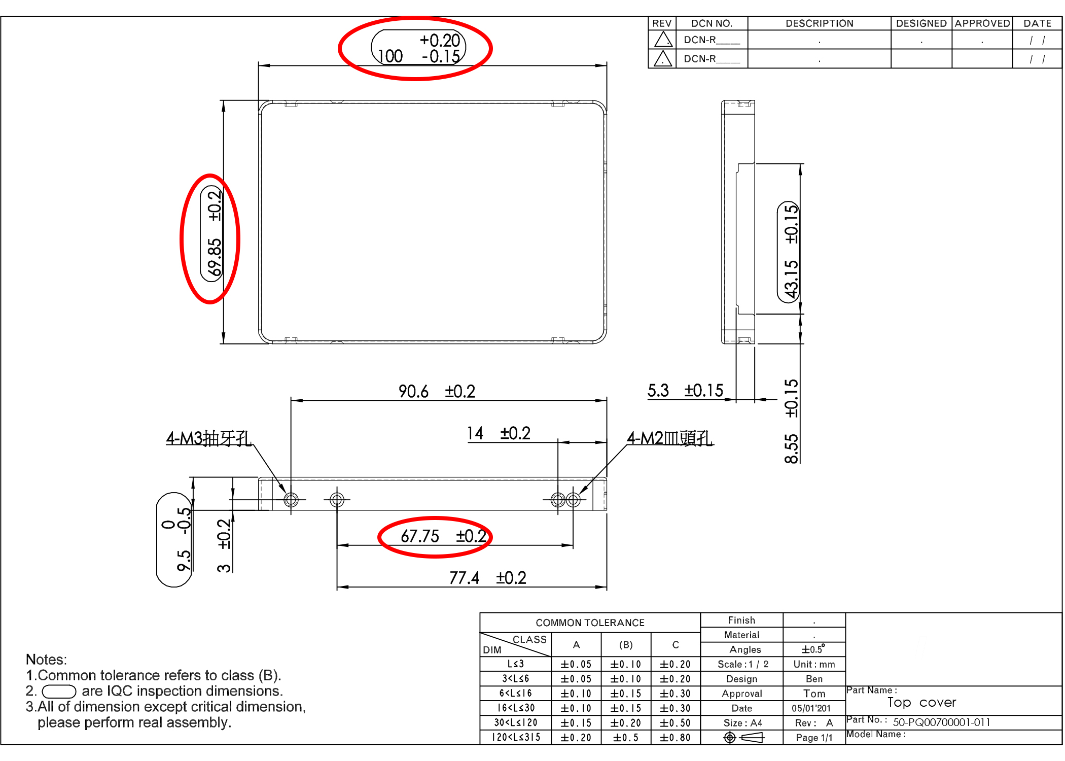
In atttached drawing sheet metal thickness is 0.8mm, when i do

How to customize color, thickness in Solidworks Drawing with the Line
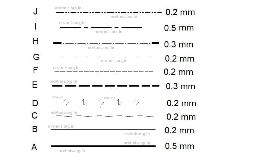
Most Important line in Engineering Drawing and their uses NCVT MIS

Adjust line thickness in Drawing mode — Onshape
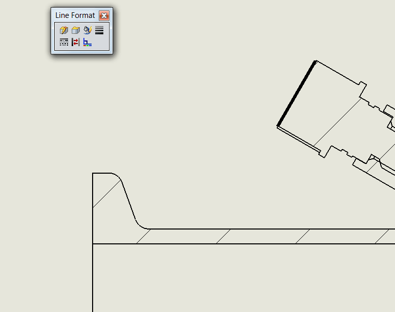
How Do You Change Line Thicknesses In A SOLIDWORKS Drawing?

Line Thickness in drawing — Onshape

In atttached drawing sheet metal thickness is 0.8mm, when i do
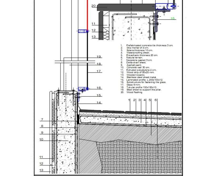
2d concrete tile thickness drawing cad file Cadbull
Web The Process Of Adding Size Information To A Drawing Is Known As Dimensioning The Drawing.
Thickness Of Lines (All Dimensions In Mm) Types Of Lines Used In Engineering Drawing.
Ation Of The Object In Figure 2 Is Called An Isometric Drawing.
Web Basic Types Of Symbols Used In Engineering Drawings Are Countersink, Counterbore, Spotface, Depth, Radius, And Diameter.
Related Post: