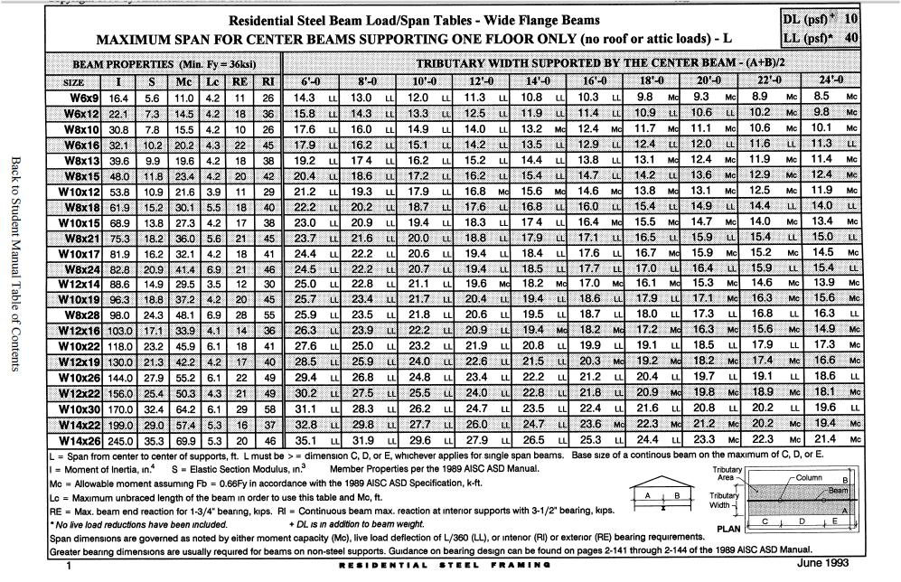
Steel I Beam Load Capacity Chart
Steel I Beam Load Capacity Chart - Minimum 4 long support a‐36 steel, 2 : Web the skyciv i beam load capacity calculator is a free tool to help structural engineers calculate the capacity (or strength) of an i beam, as defined by the aisc 360 steel design standard. Enter the width of the flange in millimeters (e.g., 200 mm). Width of the flange (b): S shapes are designated by the letter s followed by the nominal depth in inches and the weight in pounds per foot. In designing a steel i beam member, determining how much strength or capacity it has is an important step. Span is from center of support to center of support, 8 u‐head width is considered. In this calculator, we will explore the following: Enter the thickness of the flange in millimeters (e.g., 15 mm). How to calculate support reactions in a beam; Web the skyciv i beam load capacity calculator is a free tool to help structural engineers calculate the capacity (or strength) of an i beam, as defined by the aisc 360 steel design standard. Width of the flange (b): Web span (m) allowance deflection l / 360 (m) 1 span (kn/m) 2 span (kn/m) 3 span (kn/m) 1.20. Web w6x12. Minimum 4 long support a‐36 steel, 2 : In designing a steel i beam member, determining how much strength or capacity it has is an important step. Thickness of the flange (tf): Web span (m) allowance deflection l / 360 (m) 1 span (kn/m) 2 span (kn/m) 3 span (kn/m) 1.20. Width of the flange (b): Steel framing alliance steel the better builder. S shapes are designated by the letter s followed by the nominal depth in inches and the weight in pounds per foot. In this calculator, we will explore the following: Web the skyciv i beam load capacity calculator is a free tool to help structural engineers calculate the capacity (or strength) of an. Minimum 4 long support a‐36 steel, 2 : Enter the thickness of the flange in millimeters (e.g., 15 mm). In designing a steel i beam member, determining how much strength or capacity it has is an important step. Web the skyciv i beam load capacity calculator is a free tool to help structural engineers calculate the capacity (or strength) of. Span is from center of support to center of support, 8 u‐head width is considered. Width of the flange (b): Enter the width of the flange in millimeters (e.g., 200 mm). Web w6x12 steel beam load chart. Minimum 4 long support a‐36 steel, 2 : Minimum 4 long support a‐36 steel, 2 : Enter the width of the flange in millimeters (e.g., 200 mm). In this calculator, we will explore the following: How to calculate support reactions in a beam; Enter the thickness of the flange in millimeters (e.g., 15 mm). How to calculate support reactions in a beam; Web the skyciv i beam load capacity calculator is a free tool to help structural engineers calculate the capacity (or strength) of an i beam, as defined by the aisc 360 steel design standard. Minimum 4 long support a‐36 steel, 2 : In designing a steel i beam member, determining how much. Thickness of the flange (tf): Web span (m) allowance deflection l / 360 (m) 1 span (kn/m) 2 span (kn/m) 3 span (kn/m) 1.20. Web the skyciv i beam load capacity calculator is a free tool to help structural engineers calculate the capacity (or strength) of an i beam, as defined by the aisc 360 steel design standard. Minimum 4. Width of the flange (b): S shapes are designated by the letter s followed by the nominal depth in inches and the weight in pounds per foot. Enter the width of the flange in millimeters (e.g., 200 mm). Span is from center of support to center of support, 8 u‐head width is considered. Sample calculation of how to find support. Span is from center of support to center of support, 8 u‐head width is considered. Web the skyciv i beam load capacity calculator is a free tool to help structural engineers calculate the capacity (or strength) of an i beam, as defined by the aisc 360 steel design standard. S shapes are designated by the letter s followed by the. Sample calculation of how to find support reactions; Web the skyciv i beam load capacity calculator is a free tool to help structural engineers calculate the capacity (or strength) of an i beam, as defined by the aisc 360 steel design standard. Enter the thickness of the flange in millimeters (e.g., 15 mm). In designing a steel i beam member, determining how much strength or capacity it has is an important step. Minimum 4 long support a‐36 steel, 2 : Enter the width of the flange in millimeters (e.g., 200 mm). Web span (m) allowance deflection l / 360 (m) 1 span (kn/m) 2 span (kn/m) 3 span (kn/m) 1.20. Width of the flange (b): How to calculate support reactions in a beam; Thickness of the flange (tf): Span is from center of support to center of support, 8 u‐head width is considered. Steel framing alliance steel the better builder.
8 Inch Steel I Beam Load Capacity Chart

Load Bearing Capacity Of Steel I Beam Chart

Load Bearing Capacity Of Steel I Beam Chart Home Interior Design

Span Steel I Beam Load Capacity Chart

6 Inch Steel Ibeam Load Capacity Chart

I Beam Load Chart
Steel I Beam Span Chart

I Beam Load Chart

Ibeam Load Capacity Chart

Steel I Beam Load Capacity Chart
Web W6X12 Steel Beam Load Chart.
S Shapes Are Designated By The Letter S Followed By The Nominal Depth In Inches And The Weight In Pounds Per Foot.
In This Calculator, We Will Explore The Following:
Related Post: