Reflection Coefficient On Smith Chart
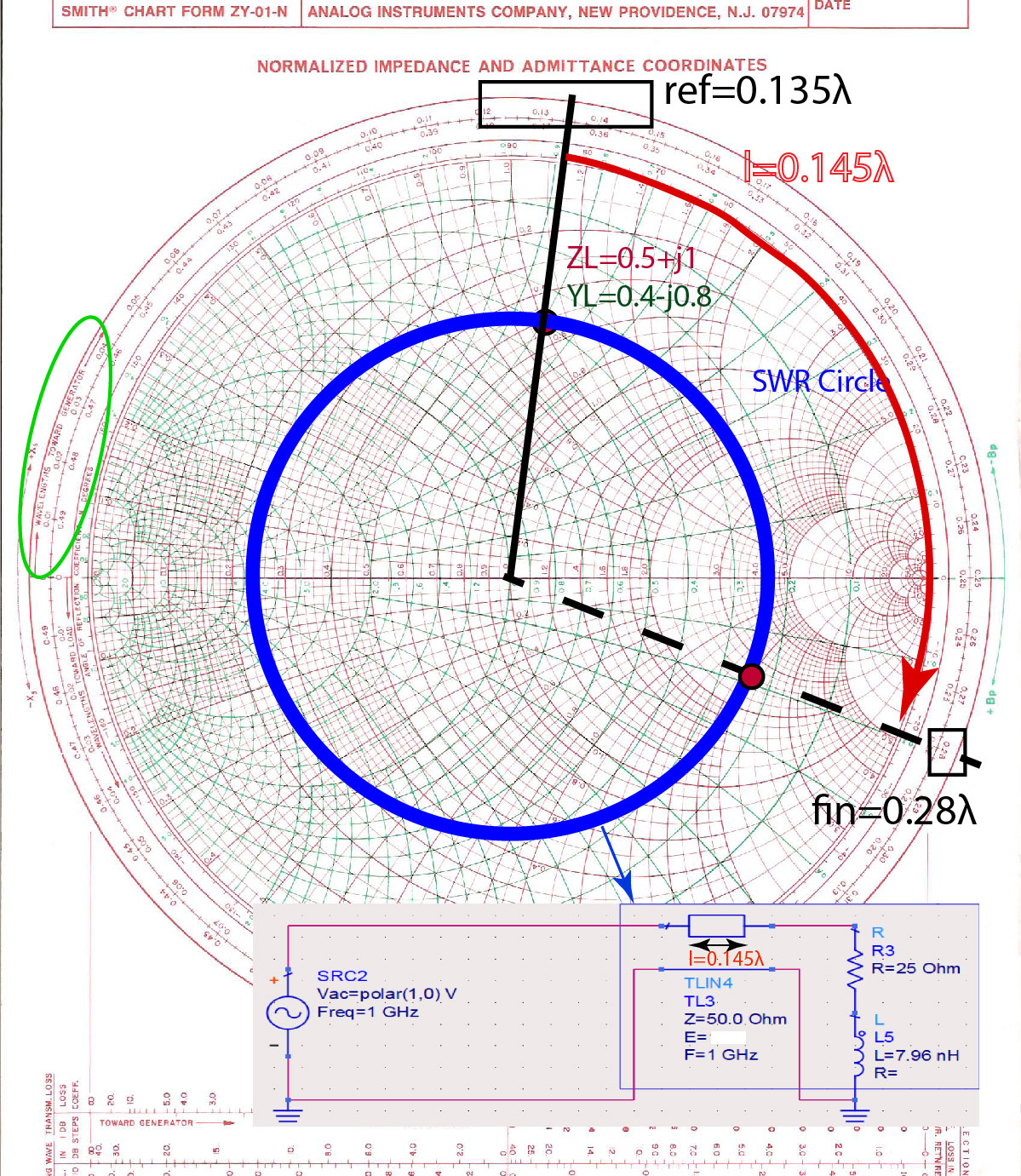
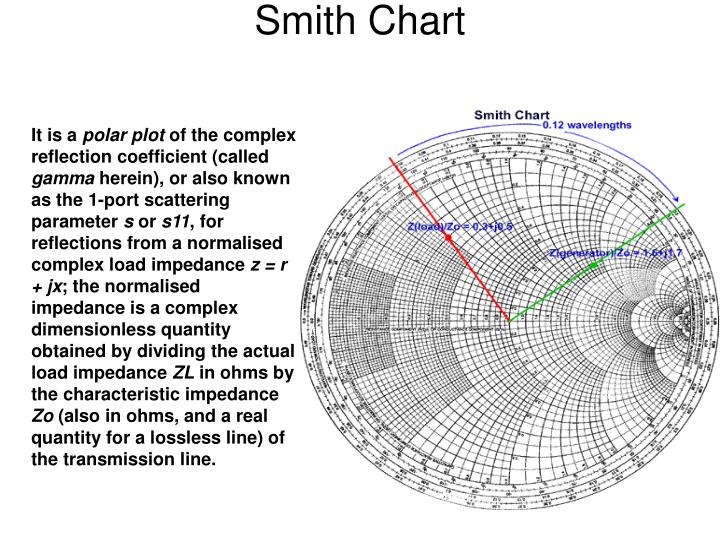
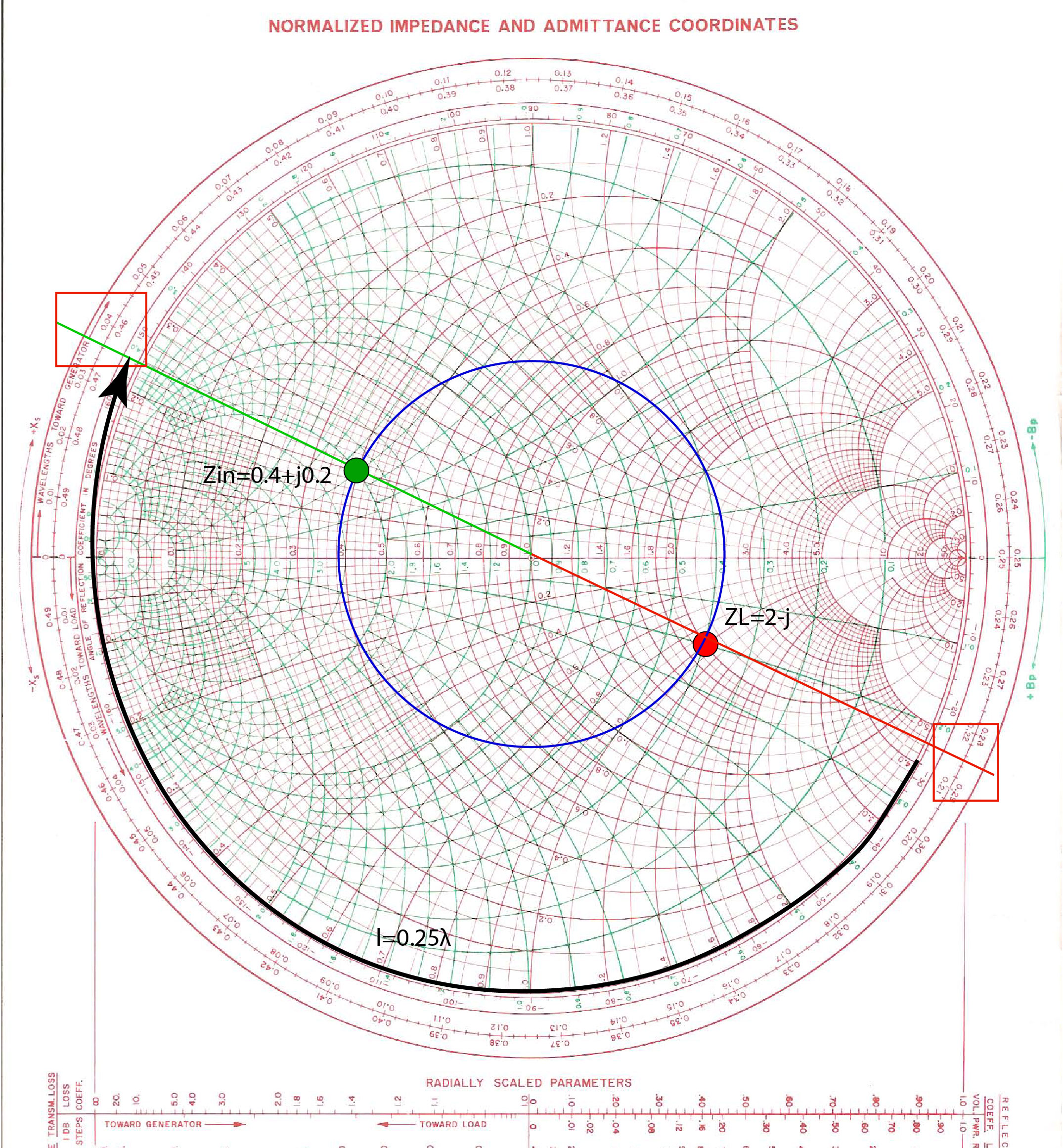
Reflection Coefficient On Smith Chart - At point a, γ = 0.6 + j0.3 = 0.67/_26.6°. Web a smith chart is the polar plot of complex reflection coefficient. Web learn how a series rlc circuit with arbitrary component values can be represented as a point on the smith chart and how an impedance contour on the smith. Web a smith chart is a graphical representation of the complex reflection coefficient, g. Web this free online interactive smith chart tool is a calculator which can help you design matching networks and obtain maximum power transfer between your source and load. Web a smith chart is commonly used to display the relationship between a reflection coefficient, typically s11 or s22, and a normalized impedance. On march 16, the 55th naacp image awards. Web by taking the standard reflection coefficient formula and manipulating it so that it provides us with the equations for circles of various radii, we'll be able to construct. Where z is the complex impedance r+jx and z0 is the characteristic impedance of the source. In smith chart terms, we want to. Basic facts and important points on the smith chart. That is, we want zl=z0 (or zin=z0). Web a smith chart is the polar plot of complex reflection coefficient. At point a, γ = 0.6 + j0.3 = 0.67/_26.6°. On march 11, bo$$ died at the age of 54. Where z is the complex impedance r+jx and z0 is the characteristic impedance of the source. Web for an open circuit (oc), the reflected voltage is equal to and in phase with the incident voltage (reflection coefficient of +1) so that the open circuit location is on the right. Web this value is the conjugate of the lna's actual input. Web this free online interactive smith chart tool is a calculator which can help you design matching networks and obtain maximum power transfer between your source and load. Web the smith chart resides in the complex plane of reflection coefficient γ = γ r + γ i = | γ | e j q = | γ |/_θ. Web to. Web the smith chart resides in the complex plane of reflection coefficient γ = γ r + γ i = | γ | e j q = | γ |/_θ. Web this free online interactive smith chart tool is a calculator which can help you design matching networks and obtain maximum power transfer between your source and load. That is,. At point a, γ = 0.6 + j0.3 = 0.67/_26.6°. Web on march 2, the brit awards 2024 were held. Casisdead won best hip hop/grime/rap act.; − 0 γ = + 0. Web the smith chart was invented by phillip smith in 1939 in order to provide an easily usable graphical representation of the complex reflection coefficient γ and reading. Basic facts and important points on the smith chart. That is, we want zl=z0 (or zin=z0). Reflection coefficient and load (z. Web the smith chart was invented by phillip smith in 1939 in order to provide an easily usable graphical representation of the complex reflection coefficient γ and reading of the. Web a smith chart is a graphical representation of. On march 16, the 55th naacp image awards. On march 11, bo$$ died at the age of 54. Web this value is the conjugate of the lna's actual input reflection coefficient (with specified load), and is given by eq. Casisdead won best hip hop/grime/rap act.; Z( z ) = z. Web on march 2, the brit awards 2024 were held. Z( z ) = z. Web definition of the smith chart, mapping the complex impedance / admittance plane with the complex reflection coefficient. Web derivation of smith chart equations. Smith charts make calculations of impedance and admittance of any transmission line simple and easy. Web derivation of smith chart equations. Web this free online interactive smith chart tool is a calculator which can help you design matching networks and obtain maximum power transfer between your source and load. Web to achieve perfect matching, we want the antenna or load impedance to match the transmission line. In smith chart terms, we want to. Web definition. Web this value is the conjugate of the lna's actual input reflection coefficient (with specified load), and is given by eq. A transmission line with a characteristic impedance of may be universally considered to have a characteristic admittance of where
any impedance, expressed in ohms, may be normalised by dividing it by the characteristic impedance, so the normalised impedance using. Smith charts make calculations of impedance and admittance of any transmission line simple and easy. Web learn how a series rlc circuit with arbitrary component values can be represented as a point on the smith chart and how an impedance contour on the smith. The relationship between impedance and reflection coefficient is given by: Web the smith chart was invented by phillip smith in 1939 in order to provide an easily usable graphical representation of the complex reflection coefficient γ and reading of the. Web as we discussed in class, the smith chart represents the complex plane of the reflection coefficient. Web a smith chart is the polar plot of complex reflection coefficient. The smith chart is basically a polar plot of the reflection coefficient(as well as some additional plots that we’ll get into shortly). Z( z ) = z. Web for an open circuit (oc), the reflected voltage is equal to and in phase with the incident voltage (reflection coefficient of +1) so that the open circuit location is on the right. Web the smith chart resides in the complex plane of reflection coefficient γ = γ r + γ i = | γ | e j q = | γ |/_θ. Web a smith chart is commonly used to display the relationship between a reflection coefficient, typically s11 or s22, and a normalized impedance. A transmission line with a characteristic impedance of may be universally considered to have a characteristic admittance of where
any impedance, expressed in ohms, may be normalised by dividing it by the characteristic impedance, so the normalised impedance using the lower case zt is given by Web on march 2, the brit awards 2024 were held. Web a smith chart is a graphical representation of the complex reflection coefficient, γ. − 0 γ = + 0. Reflection coefficient and load (z.
Reflection coefficient plot on smith chart (see online version for

How to find Reflection Coefficient using Smith Chart YouTube

Plot reflection coefficient on smith chart Tutorial 3 YouTube

Input Reflection Coefficient and Impedance on Smith Chart Ximera

Smith chart reflection coefficient calculator mondogerty
Smith chart of the reflection coefficient. Download Scientific Diagram

Input Reflection Coefficient and Impedance on Smith Chart Ximera

nanovnausersgroups.io Smith Charts showing Reflection Coefficient

Reflection coefficient smith chart nanaxnational
Smith chart of reflection coefficient against frequency Download
Smith Chart For Reflection Coefficient And Load Impedance:
Shown On The Cover Is A Chart Of Calculated Formation Energy With Respect To Cation Order Modeled Using Density Functional Theory (Dft) And.
Web Definition Of The Smith Chart, Mapping The Complex Impedance / Admittance Plane With The Complex Reflection Coefficient.
Web To Achieve Perfect Matching, We Want The Antenna Or Load Impedance To Match The Transmission Line.
Related Post: