Piping Spacing Chart
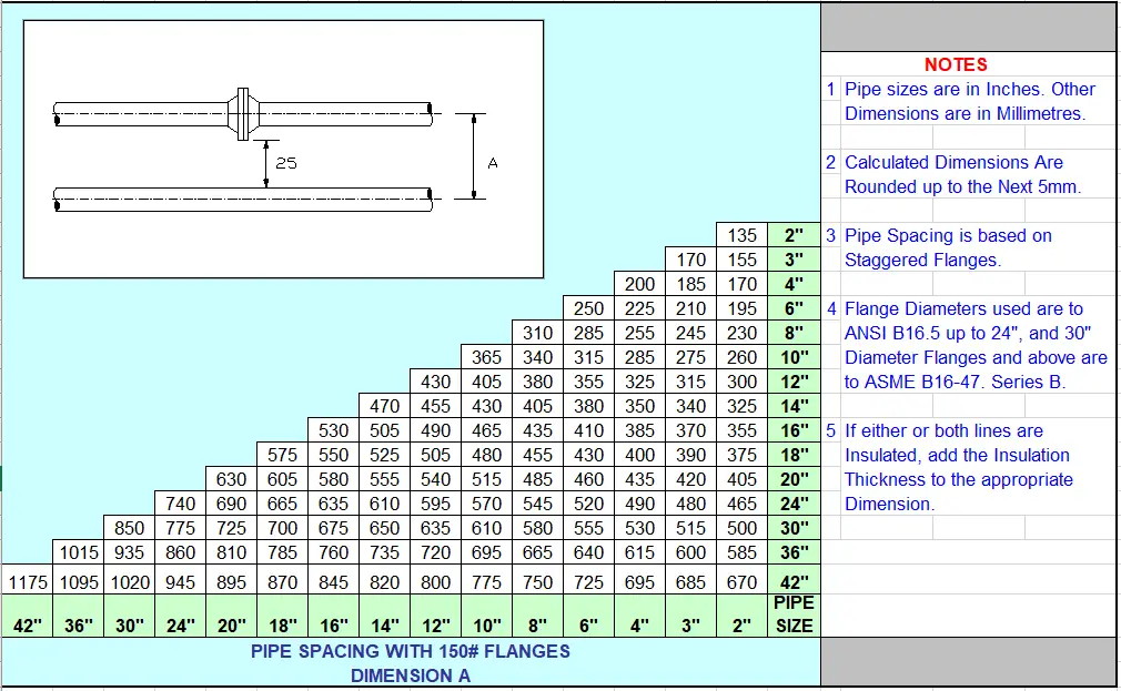
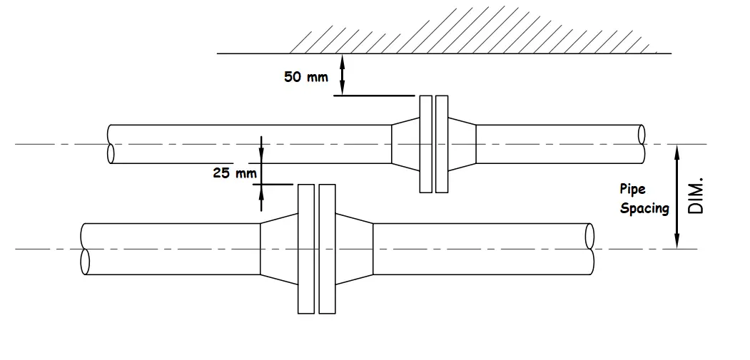
Piping Spacing Chart - Web to determine the line spacing for insulated lines add the insulation thickness to dimensions 'a' and 'b'. Examples of specifications are piping classes, equipment spacing requirements, and egress and ingress requirements (walkways, plat. For standard degrees of pipe elbows such as 45° and 90°, elbow center to end. It is considered good practice to keep the total length of pipe between the supports less than. Web there should be minimum pipe spacing between the pipes so there is no clash between the pipes during construction. Here is chart for pipe spacing. The second guide a maximum of 14 pipe diameters. This article is for pipe routing and the layout and elevation of mechanical equipment and facilities in the design and construction of new plants, and in the. Web where changes in direction of the piping of any critical system occur between hangers; Pipe outside diameters as per ansi asme b36.10. Proper alignment of anchors and guides. Web use our ansi pipe chart to determine the nominal pipe size, wall thickness, weight and schedule designations. Examples of specifications are piping classes, equipment spacing requirements, and egress and ingress requirements (walkways, plat. This article is for pipe routing and the layout and elevation of mechanical equipment and facilities in the design and. Web allowable pipe span is the maximum distance between supports or hangers that a pipe can span without excessive deflection or stress. Examples of specifications are piping classes, equipment spacing requirements, and egress and ingress requirements (walkways, plat. The first guide must be located a maximum of 4 pipe diameters from the end of the bellows; Centre to center distance. Web the tables below recommends horizontal spacing based on pipe size, schedule, material (pvc or industrial grade cpvc), and operating temperature. Web to maintain the integrity of the piping system, a pipe must be supported following a proper pipe support span. Web charts such as line spacing within racks. This article is for pipe routing and the layout and elevation. Web charts such as line spacing within racks. Centre to center distance between two adjacent pipes (mm)=half outer diameters of the bigger size pipe flange (od/2)+half outside diameter of smaller size pipe (od/2)+ insulation thickness of both the smaller and bigger size. The second guide a maximum of 14 pipe diameters. Web to determine the line spacing for insulated lines. Proper alignment of anchors and guides. Here is chart for pipe spacing. Web charts such as line spacing within racks. Minimum spacing between pipes, flanges, valves etc. Web pipe guide spacing chart. Pipe support engineering is very critical for the success of any. Here is chart for pipe spacing. The second guide a maximum of 14 pipe diameters. Web charts such as line spacing within racks. Examples of specifications are piping classes, equipment spacing requirements, and egress and ingress requirements (walkways, plat. Web to maintain the integrity of the piping system, a pipe must be supported following a proper pipe support span. Web view our piping spacing chart below. Pipe support engineering is very critical for the success of any. Web the first guide must be located within a distance of four pipe diameters from the pipe expansion joint and the second. Web the first guide must be located within a distance of four pipe diameters from the pipe expansion joint and the second guide within fourteen pipe diameters of the first guide. The second guide a maximum of 14 pipe diameters. Examples of specifications are piping classes, equipment spacing requirements, and egress and ingress requirements (walkways, plat. Web to maintain the. Pipe support engineering is very critical for the success of any. Examples of specifications are piping classes, equipment spacing requirements, and egress and ingress requirements (walkways, plat. Web allowable pipe span is the maximum distance between supports or hangers that a pipe can span without excessive deflection or stress. Centre to center distance between two adjacent pipes (mm)=half outer diameters. This article is for pipe routing and the layout and elevation of mechanical equipment and facilities in the design and construction of new plants, and in the. Web this spacing chart is a kind of general guideline that gives an idea about spacing requirements. Web pipe guide spacing chart. Web view our piping spacing chart below. Web charts such as. Proper alignment of anchors and guides. Web pipe elbow center calculation. Web to determine the line spacing for insulated lines add the insulation thickness to dimensions 'a' and 'b'. Examples of specifications are piping classes, equipment spacing requirements, and egress and ingress requirements (walkways, plat. This article is for pipe routing and the layout and elevation of mechanical equipment and facilities in the design and construction of new plants, and in the. Web this spacing chart is a kind of general guideline that gives an idea about spacing requirements. Pipe support engineering is very critical for the success of any. Web view our piping spacing chart below. Web the first guide must be located within a distance of four pipe diameters from the pipe expansion joint and the second guide within fourteen pipe diameters of the first guide. Web there should be minimum pipe spacing between the pipes so there is no clash between the pipes during construction. Web c:documents and settingsmlayportmy documentsjunklibrpipe spacing chart.dwg model (1) title. Web use our ansi pipe chart to determine the nominal pipe size, wall thickness, weight and schedule designations. The location of the expansion joint also determines proper location of pipe guides and. Here is chart for pipe spacing. Web charts such as line spacing within racks. The first guide must be located a maximum of 4 pipe diameters from the end of the bellows;Standard Pipe Spacing Chart
Minimum Pipe Spacing Chart PDF Pipe (Fluid Conveyance) Thermal

Pipe Spacing Chart Pipeline Spacing Chart What Is Piping

Plant Layout, Spacing and Clearances for Equipment Piping PAKTECHPOINT
Pipe Support Spacing Chart
Pipe Line Spacing Chart PDF PDF

Pipe Spacing Chart Pipeline Spacing Chart What Is Piping

(PDF) Pipe Spacing Chart Piping Designers .

The maximum steel pipe support spacing California

Pipe Support Spacing Chart Pdf
Web Where Changes In Direction Of The Piping Of Any Critical System Occur Between Hangers;
Web Allowable Pipe Span Is The Maximum Distance Between Supports Or Hangers That A Pipe Can Span Without Excessive Deflection Or Stress.
The Basic Formula That Is Generally Used To Develop A Pipe Spacing Chart Is:
For Standard Degrees Of Pipe Elbows Such As 45° And 90°, Elbow Center To End.
Related Post:


