Pipes Drawing
Pipes Drawing - Web various symbols are used to indicate piping components, instrumentation, equipments in engineering drawings such as piping and instrumentation diagram (p&id), isometric drawings, plot plan, equipment layout, welding drawings etc. Analyze the complicated piping arrangements. Web piping isometric drawings are detailed technical illustrations that show a 3d view of piping systems. Web with edrawmax, creating a plumbing plan is extremely easy. In other words, p&ids are schematics or diagrams that lay out the basics of a piping design for what will. Identify the type of pipe needed for your application, such as copper piping or pvc. With free templates, symbols, scalable options, and remote collaboration, you can draw a plumbing plan in a couple of minutes. Web a p&id or process and instrumentation diagram provides a detailed graphical representation of the actual process system that includes the piping, equipment, valves, instrumentation, and other process components in the system. The main purpose of a technical drawing is to communicate fabrication requirements clearly and simply. Web build your custom piping and instrumentation diagrams with professional symbols for motors, flow meters, segmented pipes, pumps, tanks, valves, sensors, process cooling, process heating, water and wastewater systems, and much more. There are different types of piping diagrams and they are process flow diagrams, piping and instrumentation diagram, orthographic pipe drawing, piping isometrics, and block flow diagrams. Turn a diagram into a working system. Web the basic elements of piping design. Pipes, elbows, tees, and dimensions. No more tedious material tracking when creating a pipe isometric drawing. These highly structured drawings provide a comprehensive 3d representation of the arrangement, dimensions, and connections of pipes within a system. Collaborate with your team on a seamless workspace no matter where they are. Charge is like the drops of water inside the pipe; Piping fabrication work is based on isometric drawings. There are usually five types of piping drawings that. The drawing axes of the isometrics intersect at an angle of 60°. Following are the basic steps you need to. Discover the essentials of piping isometrics, including how they simplify complex piping systems for construction, maintenance, and documentation purposes. Piping fabrication work is based on isometric drawings. Web piping engineering involves referencing and production of various drawings and documents. Web detailed piping drawings illustrate a selected part or an area of the piping system and offer a closer look. Piping fabrication work is based on isometric drawings. Generate diagrams from data and add data to shapes to enhance your existing visuals. In other words, p&ids are schematics or diagrams that lay out the basics of a piping design for. It is the most important deliverable of any project where piping plays a vital role. We will explain electricity by drawing an analogy to water in a pipe. Web piping and instrumentation diagrams (p&ids) are articulate drawings of a processing plan with various symbols and abbreviations that entail the piping and process equipment with its instrumentation and control machinery. These. Amongst these drawings, you will notice the size, shape, material and any particular features or circumstances of pipes, valves and. Web a p&id or process and instrumentation diagram provides a detailed graphical representation of the actual process system that includes the piping, equipment, valves, instrumentation, and other process components in the system. Discover the essentials of piping isometrics, including how. Collaborate with your team on a seamless workspace no matter where they are. Web piping isometric is a representation of a single pipe line in a process plant with exact dimensions and bill of material (bom). In other words, p&ids are schematics or diagrams that lay out the basics of a piping design for what will. Web this video explain. Web piping engineering involves referencing and production of various drawings and documents. Web the basic elements of piping design. A piping isometric drawing is a technical drawing that depicts a pipe spool or a complete pipeline using an isometric representation. He should understand the operating principles. Amongst these drawings, you will notice the size, shape, material and any particular features. Web piping and instrumentation diagrams (p&ids) are articulate drawings of a processing plan with various symbols and abbreviations that entail the piping and process equipment with its instrumentation and control machinery. These tools generate the 3d representation of the piping layout, including pipe dimensions, fittings,. There are usually five types of piping drawings that are prepared to communicate various information. Piping fabrication work is based on isometric drawings. Web detailed piping drawings illustrate a selected part or an area of the piping system and offer a closer look. Web piping drawings include (i) plot or site plan, (ii) unit plan, (iii) zone plan, (iv) equipment drawings, (v) equipment layout drawings, (vi) piping plans and elevations, and (vii) 3d (three dimensional). In other words, p&ids are schematics or diagrams that lay out the basics of a piping design for what will. Web piping drawings include (i) plot or site plan, (ii) unit plan, (iii) zone plan, (iv) equipment drawings, (v) equipment layout drawings, (vi) piping plans and elevations, and (vii) 3d (three dimensional) plant model. Amongst these drawings, you will notice the size, shape, material and any particular features or circumstances of pipes, valves and. Web build your custom piping and instrumentation diagrams with professional symbols for motors, flow meters, segmented pipes, pumps, tanks, valves, sensors, process cooling, process heating, water and wastewater systems, and much more. The drawing axes of the isometrics intersect at an angle of 60°. The piping drawings generated in fedo for a project are, plot plans; Web piping isometric is a representation of a single pipe line in a process plant with exact dimensions and bill of material (bom). There are different types of piping diagrams and they are process flow diagrams, piping and instrumentation diagram, orthographic pipe drawing, piping isometrics, and block flow diagrams. Web easy isometric is the first pipe isometric drawing app that helps users make detailed isometric drawings in the field and without the need for tedious reference materials. Turn a diagram into a working system. Web with edrawmax, creating a plumbing plan is extremely easy. Analyze the complicated piping arrangements. These tools generate the 3d representation of the piping layout, including pipe dimensions, fittings,. Web piping isometrics are generally produced from orthographic drawings and are important pieces of information to engineers. Reference documents are provided by other engineering departments such as process, mechanical etc. Not everyone was a fan of the festivities, however.
Plumbing Pipes Vector at Collection of Plumbing Pipes
Hand drawn wooden tobacco pipe Download Free Vectors, Clipart
![]()
How To Draw A Pipe
Pipe Drawing at GetDrawings Free download

Premium Photo A watercolor drawing of various pipes and valves.
Pipe Sketch at Explore collection of Pipe Sketch

Pin by Angela Harvey on Funky Inspiration Plumbing pipes, Plumbing
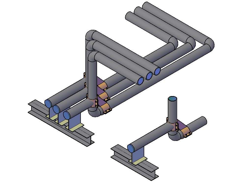
3D Pipe Drawing In AutoCAD File Cadbull

How To Draw A Pipe
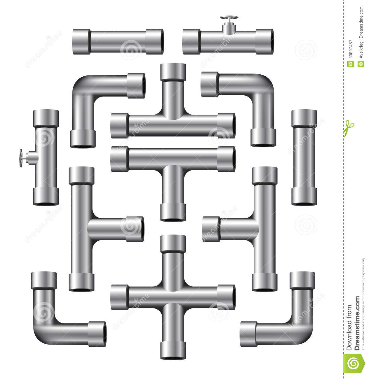
Pipes clipart 20 free Cliparts Download images on Clipground 2024
The Main Aim Of The Piping Design Is To Lay Equipment, Piping, And Other Accessories Meeting The Relevant Standards, Statutory Regulations, And Safety Requirements.
The Main Purpose Of A Technical Drawing Is To Communicate Fabrication Requirements Clearly And Simply.
Piping Fabrication Work Is Based On Isometric Drawings.
Charge Is Like The Drops Of Water Inside The Pipe;
Related Post: