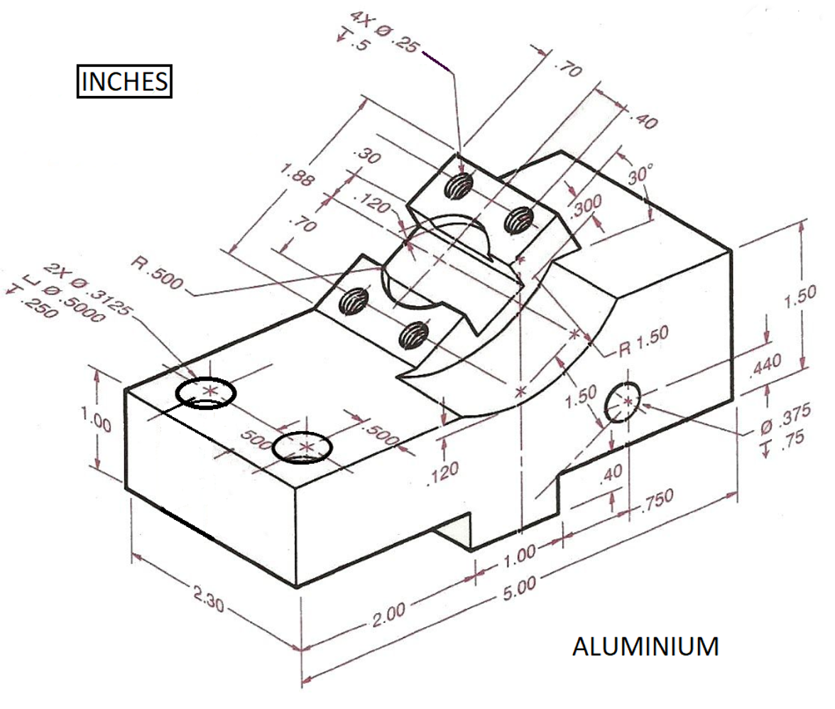
Phantom Lines In Engineering Drawing
Phantom Lines In Engineering Drawing - Phantom lines are used to indicate imaginary features. For example, holes require center lines to identify the center and show that it is round. The alphabet of lines and the. Learn about the 12 types of lines used in engineering drawings, such as visible, hidden, section, center, dimension, extension, leader, cutting plane, break, phanto… For example, they are used to indicate the alternate positions of moving parts, and adjacent positions. Web the gsfc engineering drawing standards manual is the official source for the requirements and interpretations to be used in the development and presentation of. 451 views 3 years ago #phantomline #applicationoflines #linetypes. In this lecture we will learn. Web certain features on a engineering drawing requires specific ways of indication. Web engineering drawing is a specialized form of communication that uses a strict set of symbols, standards, and perspectives to depict mechanical, electrical, or. Web ah auto cad. Web the alphabet of lines is a set of standard line types established by the american national standards institute (ansi) for technical drawing. Web engineering drawing is a specialized form of communication that uses a strict set of symbols, standards, and perspectives to depict mechanical, electrical, or. Represent the outline of an adjacent part,. Phantom lines. Web engineering lines are graphical representations used in technical drawings to communicate information about the shape, size, and features of objects. Learn about the 12 types of lines used in engineering drawings, such as visible, hidden, section, center, dimension, extension, leader, cutting plane, break, phanto… Used to show where the object is being cut. A variety of line styles graphically. Web standard engineering drawing line types. Web lines used in section views. Web learn about the 10 different types of lines recommended by the bureau of indian standards for general engineering drawings. The long dashes may vary in length, depending on the size of the drawing. Phantom lines are used to indicate imaginary features. A variety of line styles graphically represent physical objects. The long dashes may vary in length, depending on the size of the drawing. In this lecture we will learn. 451 views 3 years ago #phantomline #applicationoflines #linetypes. Represent the outline of an adjacent part,. Used to show where the object is being cut. (phantom line type) section lines: 451 views 3 years ago #phantomline #applicationoflines #linetypes. Web engineering lines are graphical representations used in technical drawings to communicate information about the shape, size, and features of objects. Learn about the 12 types of lines used in engineering drawings, such as visible, hidden, section, center,. The long dashes may vary in length, depending on the size of the drawing. Represent the outline of an adjacent part,. (phantom line type) section lines: 451 views 3 years ago #phantomline #applicationoflines #linetypes. The alphabet of lines and the. 451 views 3 years ago #phantomline #applicationoflines #linetypes. In this lecture we will learn. (phantom line type) section lines: For example, they are used to indicate the alternate positions of moving parts, and adjacent positions. The alphabet of lines and the. Web phantom lines consist of long dashes separated by pairs of short dashes (fig. In this lecture we will learn. Web the gsfc engineering drawing standards manual is the official source for the requirements and interpretations to be used in the development and presentation of. Types of lines include the following: Web learn about the 10 different types of lines. The long dashes may vary in length, depending on the size of the drawing. Web centerlines are one of the most frequently used tools in engineering drawing. For example, holes require center lines to identify the center and show that it is round. Web engineering drawing is a specialized form of communication that uses a strict set of symbols, standards,. A variety of line styles graphically represent physical objects. The alphabet of lines and the. Represent an object's invisible edges and outlines, these features can't be seen from the drawing's view. Web standard engineering drawing line types. Web the alphabet of lines is a set of standard line types established by the american national standards institute (ansi) for technical drawing. Web learn about the 10 different types of lines recommended by the bureau of indian standards for general engineering drawings. Used to indicate where the cutting plane cuts the. Web phantom lines consist of long dashes separated by pairs of short dashes (fig. Web ah auto cad. Their basic purpose is to show circular/cylindrical features in a drawing, which are found. Web centerlines are one of the most frequently used tools in engineering drawing. Web engineering lines are graphical representations used in technical drawings to communicate information about the shape, size, and features of objects. In this lecture we will learn. (phantom line type) section lines: The alphabet of lines and the. 451 views 3 years ago #phantomline #applicationoflines #linetypes. Web standard engineering drawing line types. Types of lines include the following: For example, holes require center lines to identify the center and show that it is round. Represent an object's invisible edges and outlines, these features can't be seen from the drawing's view. Web certain features on a engineering drawing requires specific ways of indication.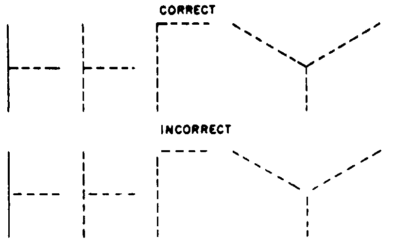
Phantom Line Engineering
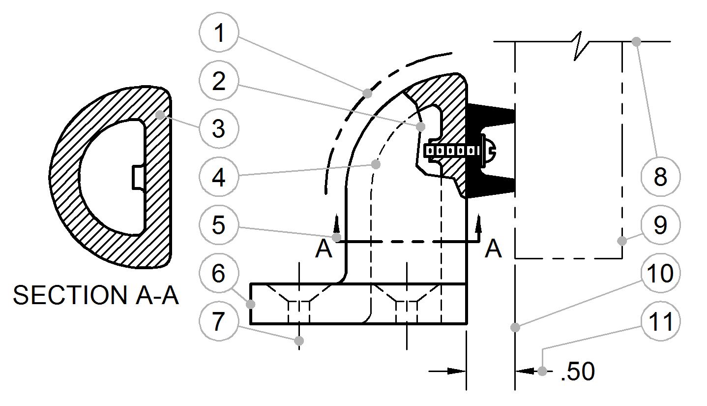
Section Line Drafting
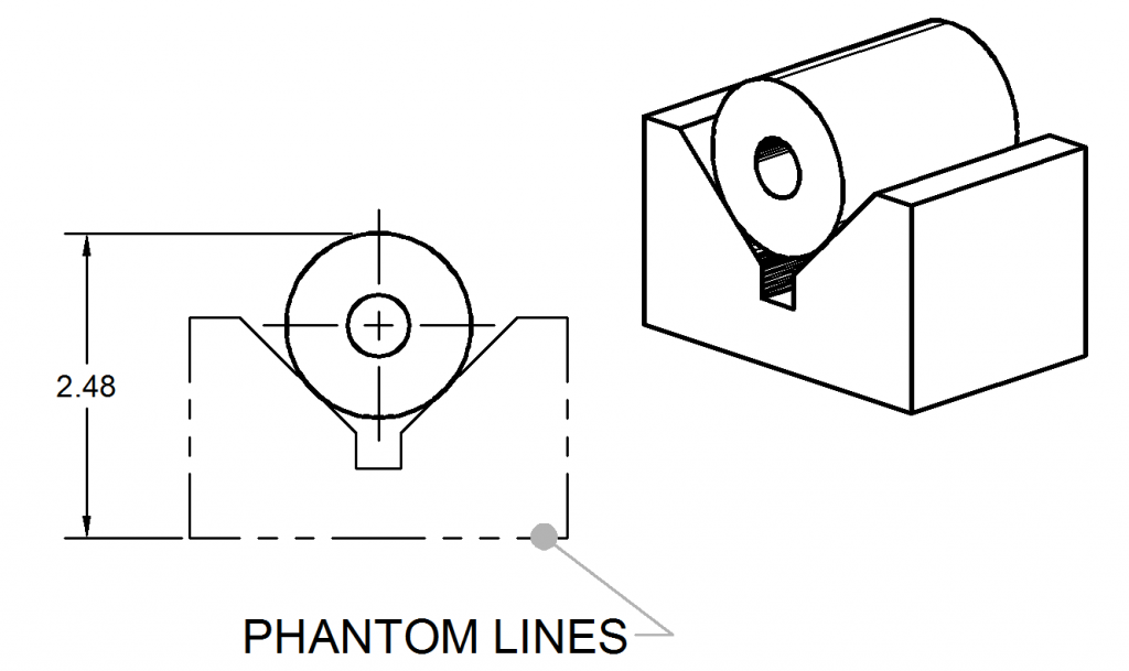
Phantom Lines ToolNotes

Type of Line used in (ED) Engineering Drawing Phantom line hidden

Adding phantom lines in SketchUp FineWoodworking
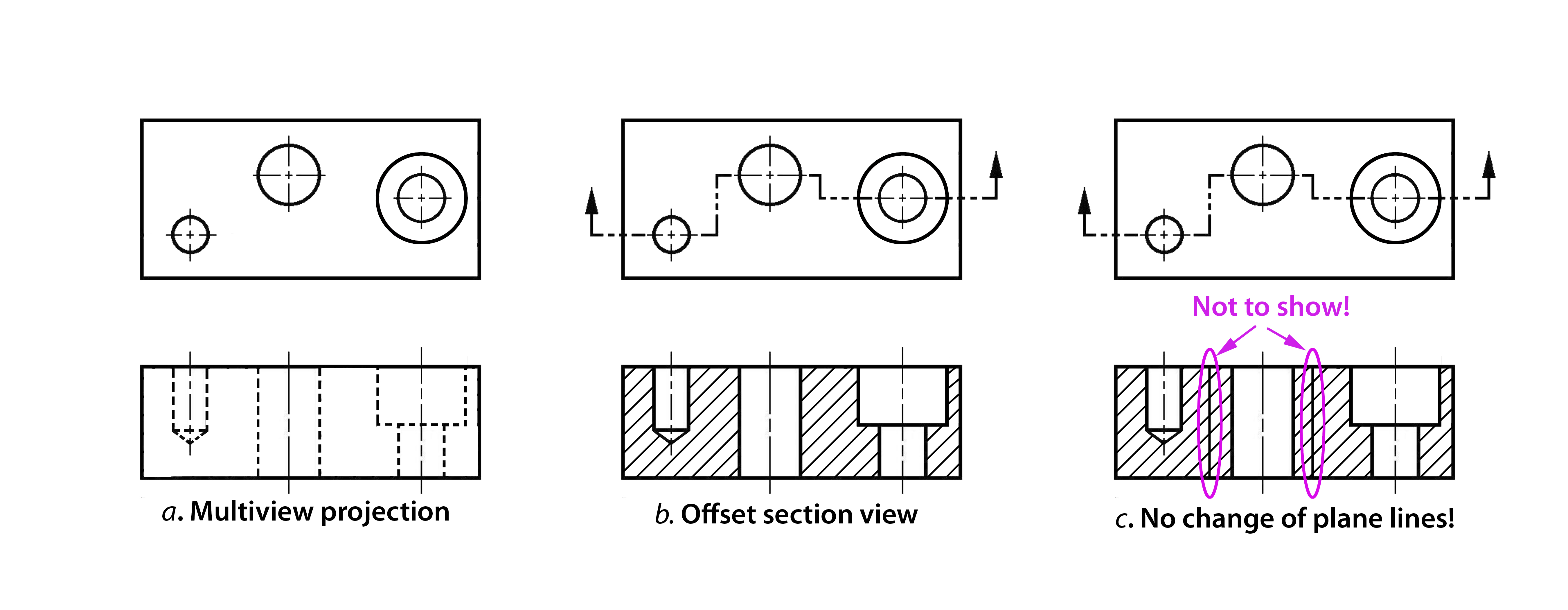
How to Draw Sectronal View From Phantom Line Cunningham Youbtand
Solved Phantom Lines in Inventor 2016 Autodesk Community
Solved Draw the required orthographic views (included
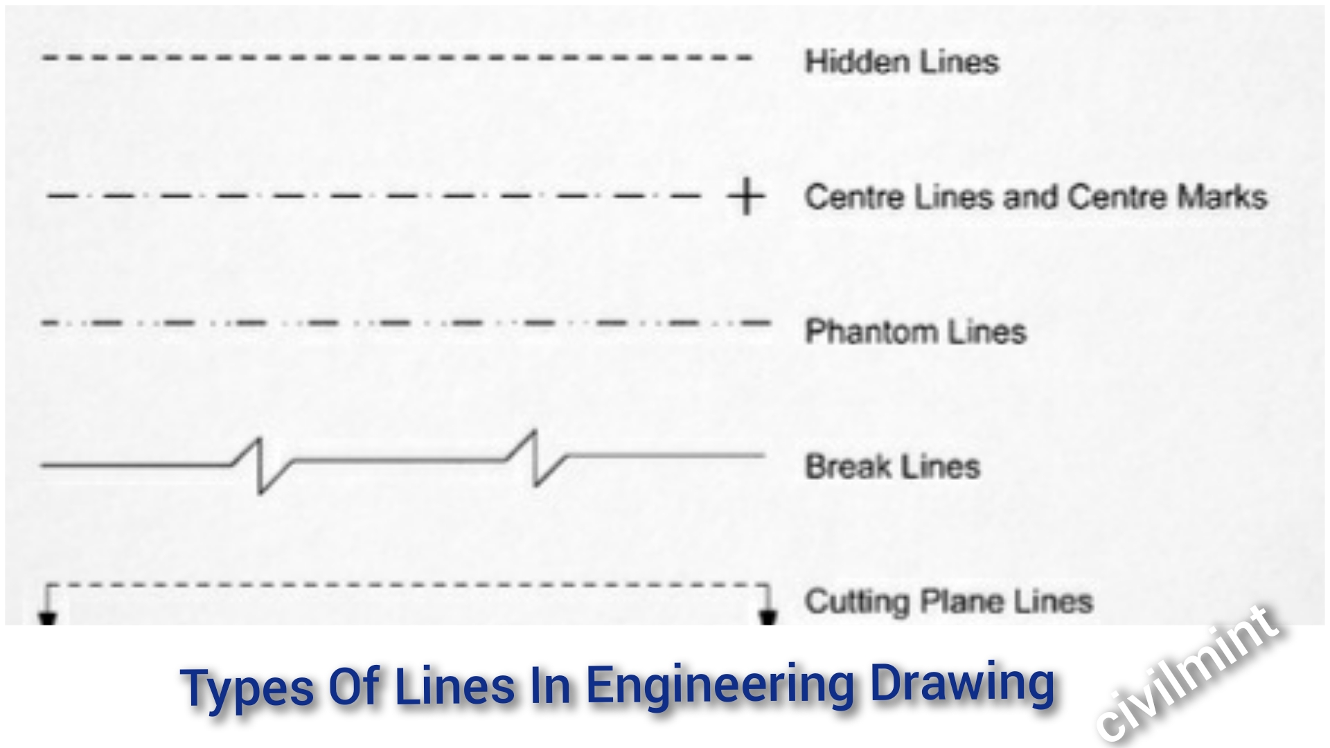
27 Different Types Of Lines In Drawing Pics Drawer Ri vrogue.co
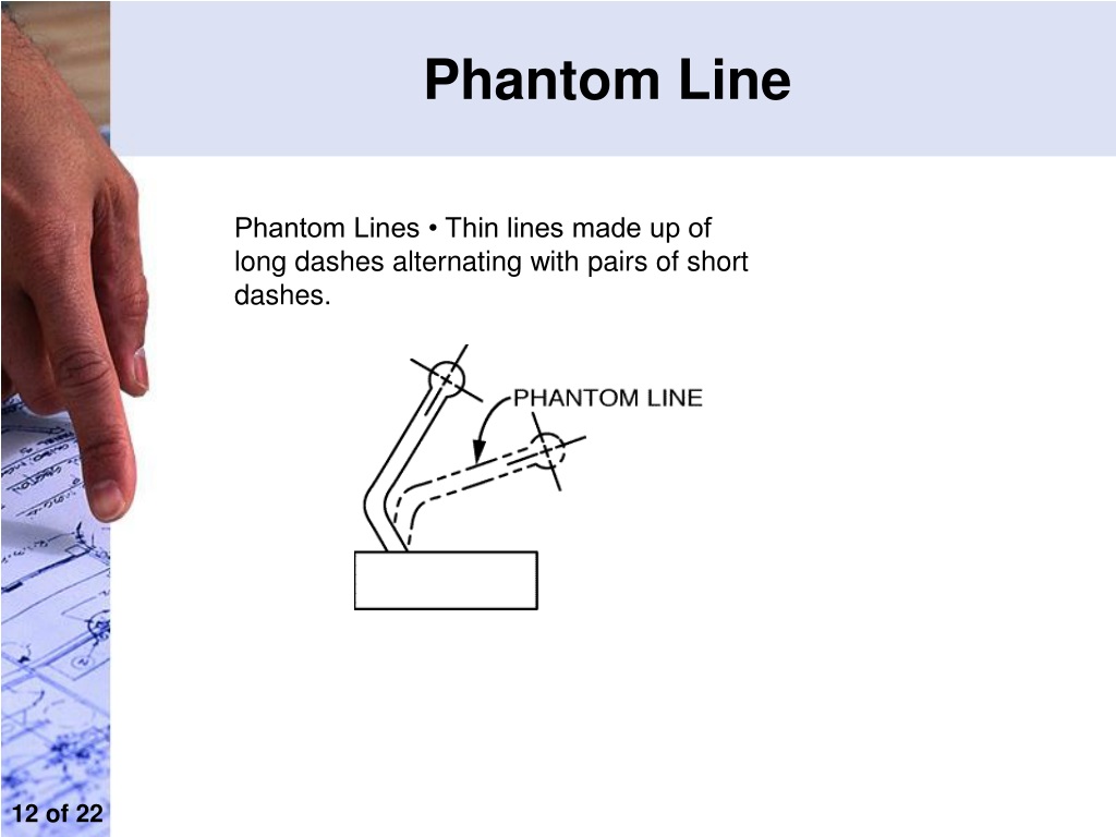
PPT Engineering Drawing PowerPoint Presentation, free download ID
Web The Alphabet Of Lines Is A Set Of Standard Line Types Established By The American National Standards Institute (Ansi) For Technical Drawing.
Web Engineering Drawing Is A Specialized Form Of Communication That Uses A Strict Set Of Symbols, Standards, And Perspectives To Depict Mechanical, Electrical, Or.
A Variety Of Line Styles Graphically Represent Physical Objects.
Web Lines Used In Section Views.
Related Post:

