Patch Antenna Design
Patch Antenna Design - At frequencies lower than microwave, microstrip patches don't make sense because of the sizes required. Web all of the parameters in a rectangular patch antenna design ( l, w, h, permittivity) control the properties of the antenna. Learn about their function, compact size, and directional radiation. Welcome to our module in building the patch antenna. , a cross shaped slot was used to excite microstrip radiation patches, significantly improving polarisation isolation, but its application in the array was not considered. A compact rectangular patch antennas are designed and tested for gps devices at 1.57542 ghz, and for a satellite tv signal at 11.843 ghz and 11.919 ghz. Web here is the link page to the various patch antenna and microstrip antenna topics. The goal is to understand the radiation mechanism, polarization, patterns, impedance and bandwidth; Web also called “patch antennas” one of the most useful antennas at microwave frequencies (f > 1 ghz). Web discover the construction and advantages of microstrip patch antennas in wireless communication. Web discover the construction and advantages of microstrip patch antennas in wireless communication. Web pasternack's microstrip patch antenna calculator determines the length and width (in millimeters) of a rectangular patch antenna. A larger bandwidth and sufficient return loss are offered by the square microstrip antenna in. , a cross shaped slot was used to excite microstrip radiation patches, significantly improving. Web a patch antenna, also known as a microstrip antenna, is a type of radio antenna with a low profile that can be mounted on a flat surface. The general dimensions are /2, however due to the specific dynamics of the antenna and the fringing fields, the exact dimensions require more careful calculations. The effect of the offset on the. Both antennas used microstrip line for feeding. Signal reception and transmission on vehicle rooftops, and address ba ndwidth constraints. Web pasternack's microstrip patch antenna calculator determines the length and width (in millimeters) of a rectangular patch antenna. Web in this article, we’ll present the main equations used to design a microstrip patch antenna that provides operation in a fundamental mode,. Web all of the parameters in a rectangular patch antenna design ( l, w, h, permittivity) control the properties of the antenna. Web in this lab, we will design and simulate a patch antenna at a frequency of 1ghz. Web here is the link page to the various patch antenna and microstrip antenna topics. Generally, patch antenna has a shape. Web discover the construction and advantages of microstrip patch antennas in wireless communication. This is the antenna we’re going to build today. Open ads, create a workspace for this design. The design includes uncertainty for the patch and ground plane width. Web here is the link page to the various patch antenna and microstrip antenna topics. The effect of the offset on the perturbation segment and the design of a simple matching net. Web the microstrip patch antenna calculator determines the length (l) and width (w) of a rectangular microstrip patch antenna for a given resonant frequency or vice versa. The patch may be in a variety of shapes, but rectangular and circular are the most. The effect of the offset on the perturbation segment and the design of a simple matching net. A small 4 × 4 array is shown in figure 2 below with patch antennas as the radiators. Web discover the construction and advantages of microstrip patch antennas in wireless communication. , a cross shaped slot was used to excite microstrip radiation patches,. By gary breed editorial director. Web also called “patch antennas” one of the most useful antennas at microwave frequencies (f > 1 ghz). Web pasternack's microstrip patch antenna calculator determines the length and width (in millimeters) of a rectangular patch antenna. Welcome to our module in building the patch antenna. Signal reception and transmission on vehicle rooftops, and address ba. The goal is to match the input impedance (zin) to the transmission line (z0). Now we want to design a patch antenna like this: Web microstrip patch antenna consists of a conducting patch on one side of a dielectric substrate whose other side is grounded. Web also called “patch antennas” one of the most useful antennas at microwave frequencies (f. Web also called “patch antennas” one of the most useful antennas at microwave frequencies (f > 1 ghz). A small 4 × 4 array is shown in figure 2 below with patch antennas as the radiators. This article primarily provides the design equations for patch antennas in a pcb. Web a patch antenna, also known as a microstrip antenna, is. The patch may be in a variety of shapes, but rectangular and circular are the most common. The goal is to match the input impedance (zin) to the transmission line (z0). This design aims to op timize impedance matching, improv e. Web the microstrip patch antenna calculator determines the length (l) and width (w) of a rectangular microstrip patch antenna for a given resonant frequency or vice versa. By gary breed editorial director. Web all of the parameters in a rectangular patch antenna design ( l, w, h, permittivity) control the properties of the antenna. Web this article describes the design of a compact, circular polarized (cp), nearly square patch antenna using an offset microstrip feed and operating at 2.45 ghz. This antenna has several advantages, including a higher degree of directivity and an overall low cost. And you can see it consists of a patch on the right, and then an impedance matching transmission line on the left. Web here is the link page to the various patch antenna and microstrip antenna topics. The final part of this work has been concentrated on studying an. It consists of a flat rectangular, circular or other shaped conducting patch mounted on a. Web the typical implementation of this array uses patch antenna elements configured in equally spaced rows and columns with a 4 × 4 design implying 16 total elements. This is the antenna we’re going to build today. This article primarily provides the design equations for patch antennas in a pcb. Web based rectangular patch antenna is proposed.
Microstrip Patch Antenna Designing HFSS TUTORIAL YouTube

HFSS Tutorial 5 Patch Antenna Create, Simulate & Analyze Probe

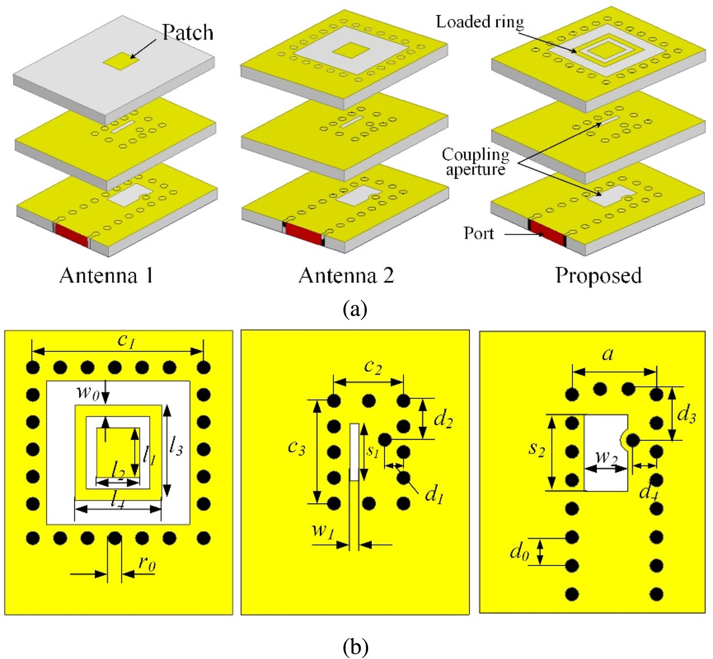
Highgain cavity backed patch antenna arrays at 140 GHz based on LTCC

Schematic of patch antenna designed by HFSS Download Scientific Diagram

7 Patch antenna with a quarterwavelength matching section. Download

915MHz Patch Antenna Saturn PCB Design Saturn PCB Design

Patch Antennas Radartutorial

Kaband antenna arrays with dualfrequency and dualpolarized patch

Design Simulation of 2x2 Antenna Patch Array Using Keysight ADS YouTube

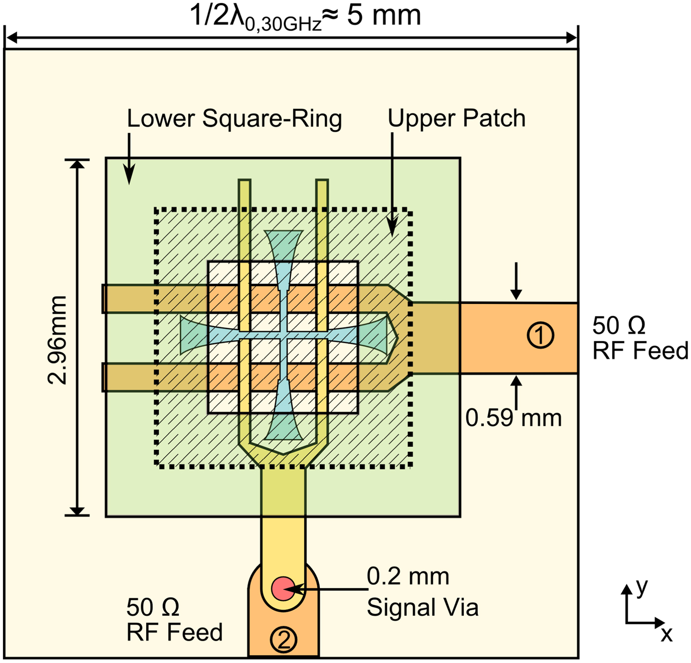
Aperture coupled patch antenna. Download Scientific Diagram
Web A Patch Antenna, Also Known As A Microstrip Antenna, Is A Type Of Radio Antenna With A Low Profile That Can Be Mounted On A Flat Surface.
A Small 4 × 4 Array Is Shown In Figure 2 Below With Patch Antennas As The Radiators.
A Larger Bandwidth And Sufficient Return Loss Are Offered By The Square Microstrip Antenna In.
It Usually Consists Of A Metal “Patch” On Top Of A Grounded Dielectric Substrate.
Related Post: