Motor Schematic Drawing
Motor Schematic Drawing - It typically consists of a simple diagram that outlines the positive and. Web welcome to module 16, which is about the basics of motors and motor control. Web line diagrams, also called “ schematic ” or “ elementary ” diagrams, show the circuits which form the basic operation of the controller. Web motor control circuits are often connected to lower voltages than the motor they control to make it safer for operators and maintenance personnel. Web an electrical schematic is a diagram that shows how all of the wires and components in an electronic circuit are connected. Web a dc motor wiring diagram will quickly show you the connections between these components. They’re like a map for building or. Web the schematic diagram of an electric motor typically includes components such as a rotor, stator, commutator, brushes, and a power supply. These diagrams depict the electrical connections and components of a. Web the diagram shows how the commutator (in green) and brushes (in red) work together to let current flow to the electromagnet, and also to flip the direction that the. Web an electric motor diagram is a visual representation of how the various components of an electric motor are connected. It typically consists of a simple diagram that outlines the positive and. These diagrams depict the electrical connections and components of a. Web the following are the typical parts of a motor. It shows the wiring and connections between the. They do not indicate the. Web line diagrams, also called “ schematic ” or “ elementary ” diagrams, show the circuits which form the basic operation of the controller. Web motor control circuits are often connected to lower voltages than the motor they control to make it safer for operators and maintenance personnel. Web the schematic diagram of an electric. Web a dc motor wiring diagram will quickly show you the connections between these components. Web three phase motor connection schematic, power and control wiring installation diagrams. Web an electric motor diagram is a visual representation of how the various components of an electric motor are connected. Web line diagrams, also called “ schematic ” or “ elementary ” diagrams,. Web motor control circuits are often connected to lower voltages than the motor they control to make it safer for operators and maintenance personnel. Web motor control circuit diagrams are essential tools for understanding and designing motor control systems. Web an electrical schematic is a diagram that shows how all of the wires and components in an electronic circuit are. Learn how a dc motor works to understand the basic working principle of a dc motor. Web line diagrams, also called “ schematic ” or “ elementary ” diagrams, show the circuits which form the basic operation of the controller. Web the schematic diagram of an electric motor typically includes components such as a rotor, stator, commutator, brushes, and a. Learn how a dc motor works to understand the basic working principle of a dc motor. Web line diagrams, also called “ schematic ” or “ elementary ” diagrams, show the circuits which form the basic operation of the controller. Web motor control circuits are often connected to lower voltages than the motor they control to make it safer for. Web motor control circuits are often connected to lower voltages than the motor they control to make it safer for operators and maintenance personnel. These diagrams depict the electrical connections and components of a. It shows the wiring and connections between the power. It typically consists of a simple diagram that outlines the positive and. They do not indicate the. Web the diagram shows how the commutator (in green) and brushes (in red) work together to let current flow to the electromagnet, and also to flip the direction that the. Web welcome to module 16, which is about the basics of motors and motor control. We consider conventional current, electron flow, the. It shows the wiring and connections between the. Web welcome to module 16, which is about the basics of motors and motor control. Web three phase motor connection schematic, power and control wiring installation diagrams. An electric motor is a machine that converts electrical energy to mechanical energy. Web a dc motor wiring diagram will quickly show you the connections between these components. They’re like a map for. Web welcome to module 16, which is about the basics of motors and motor control. These diagrams depict the electrical connections and components of a. Web line diagrams, also called “ schematic ” or “ elementary ” diagrams, show the circuits which form the basic operation of the controller. Web the diagram shows how the commutator (in green) and brushes. Web welcome to module 16, which is about the basics of motors and motor control. We consider conventional current, electron flow, the. Web an electric motor diagram is a visual representation of how the various components of an electric motor are connected. Web line diagrams, also called “ schematic ” or “ elementary ” diagrams, show the circuits which form the basic operation of the controller. Web the diagram shows how the commutator (in green) and brushes (in red) work together to let current flow to the electromagnet, and also to flip the direction that the. These diagrams depict the electrical connections and components of a. Web motor control circuit diagrams are essential tools for understanding and designing motor control systems. Web the schematic diagram of an electric motor typically includes components such as a rotor, stator, commutator, brushes, and a power supply. They’re like a map for building or. Web the following are the typical parts of a motor. It typically consists of a simple diagram that outlines the positive and. It shows the wiring and connections between the power. Web an electrical schematic is a diagram that shows how all of the wires and components in an electronic circuit are connected. Web a dc motor wiring diagram will quickly show you the connections between these components. They do not indicate the.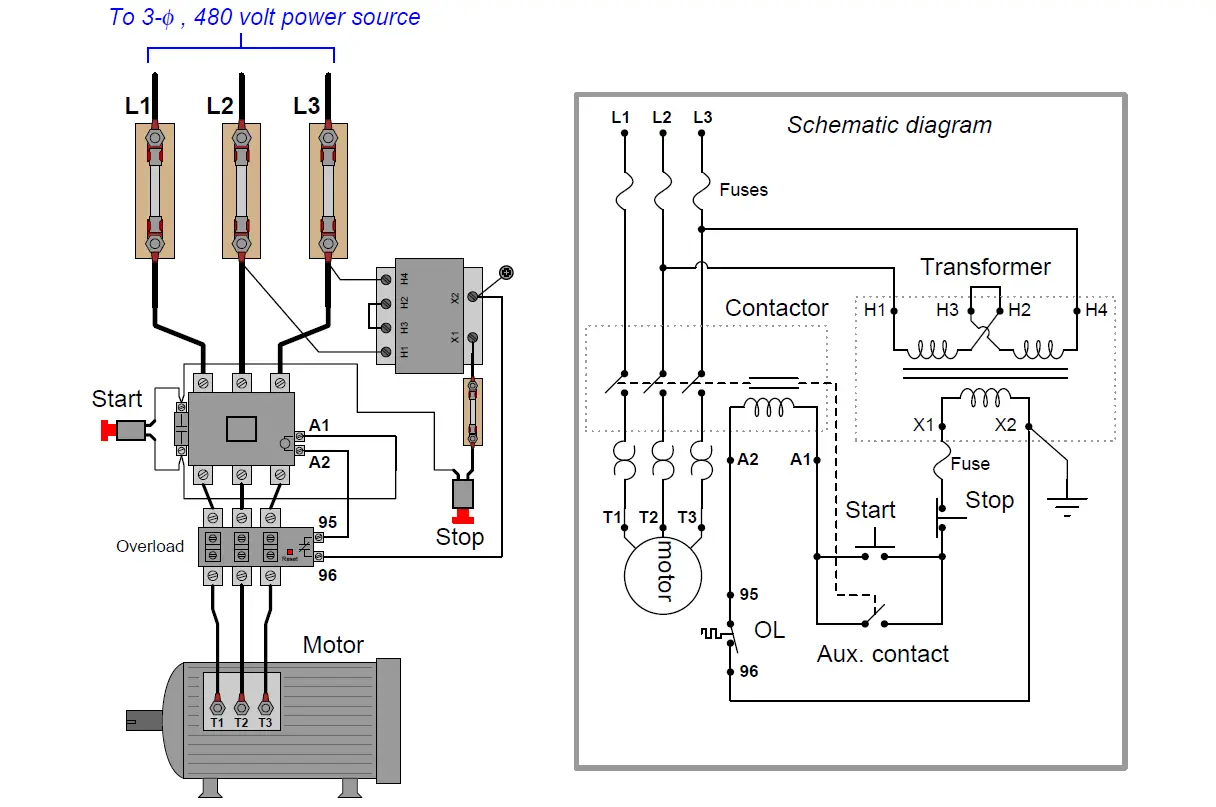
Electric Motor Circuit Diagram
Schematic Diagram Of Single Phase Motor
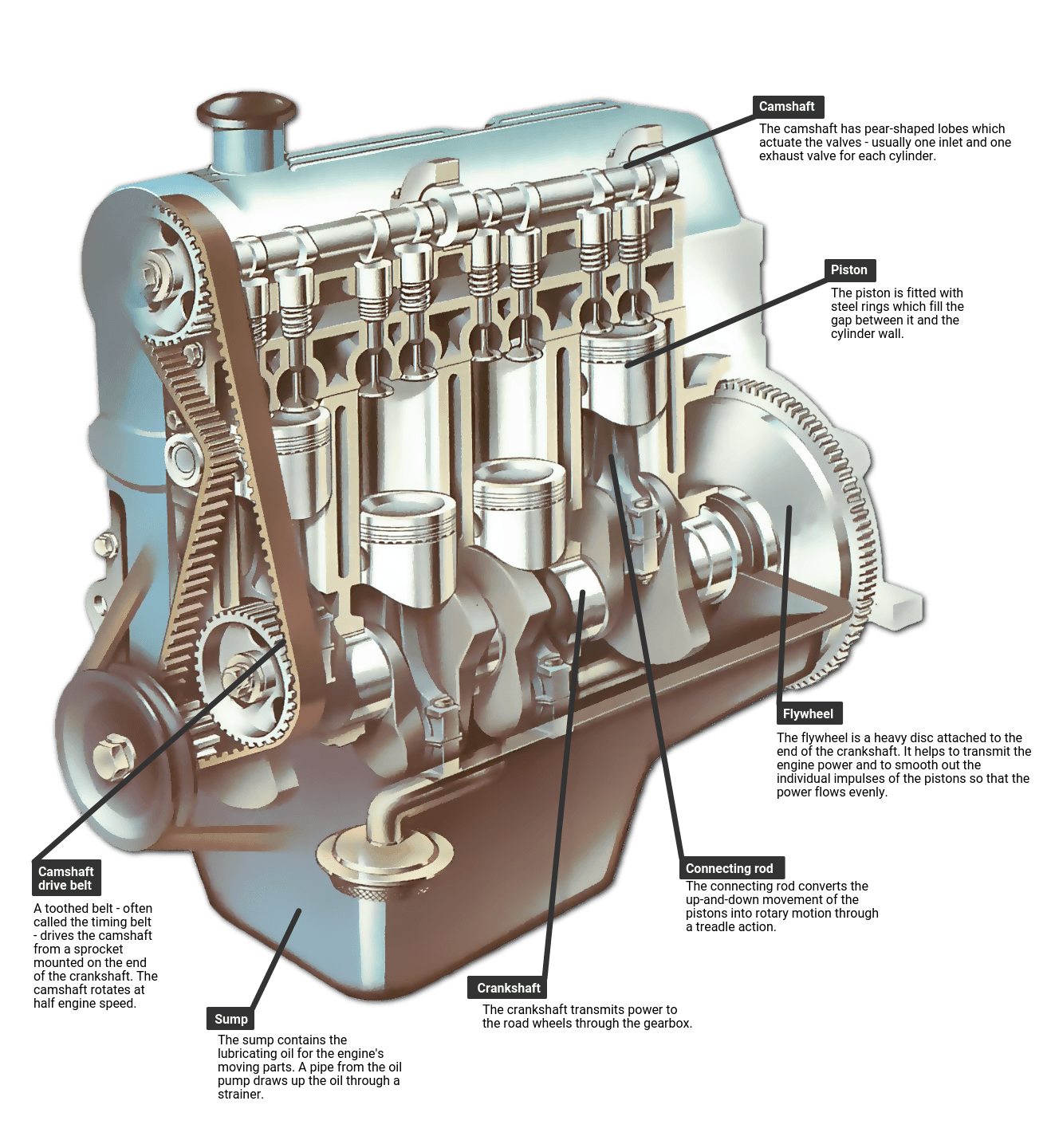
Diagram Car Motor
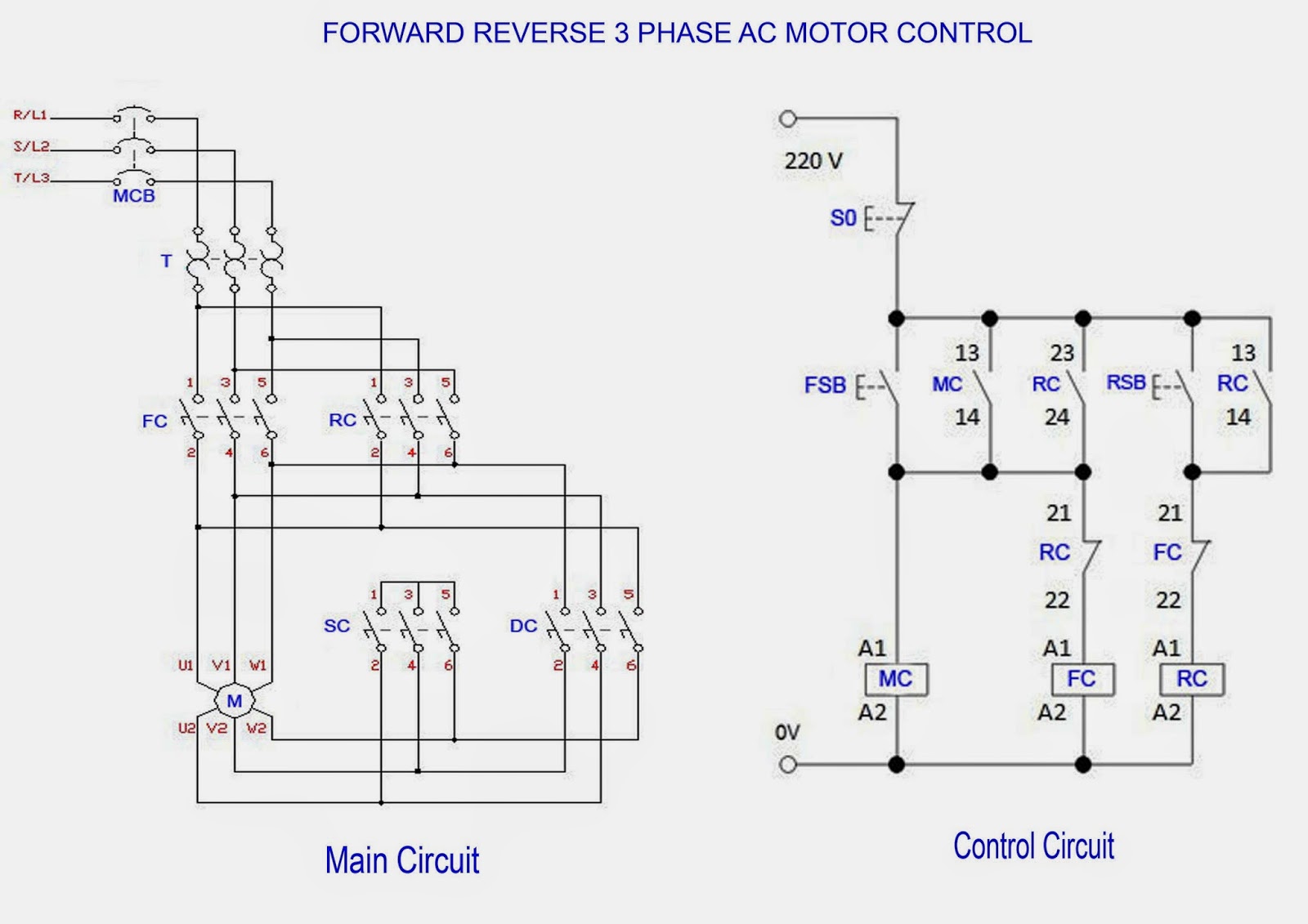
3 Phase Motor Control Circuit Diagram
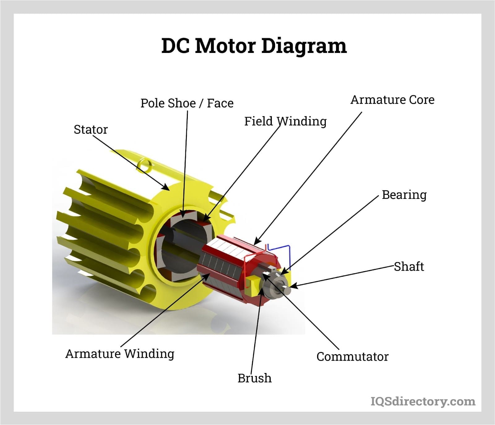
Electric Motors Types, Applications, Construction, and Benefits
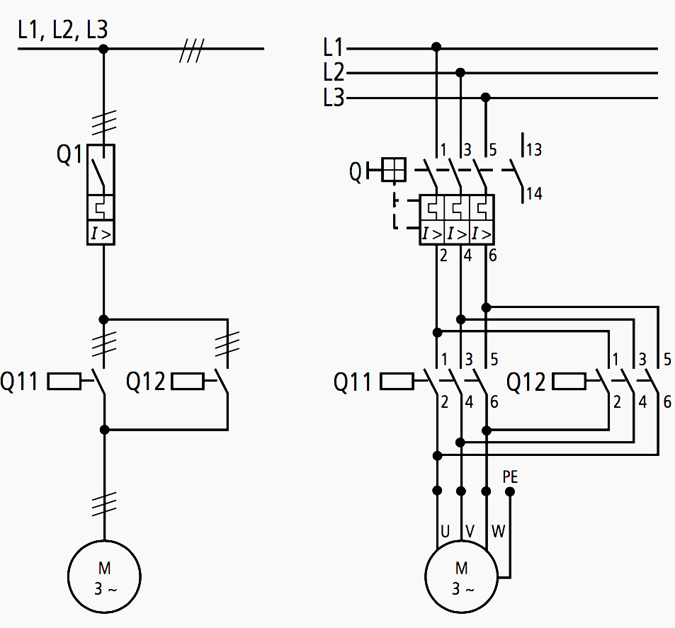
Electric Circuit Diagram Motor
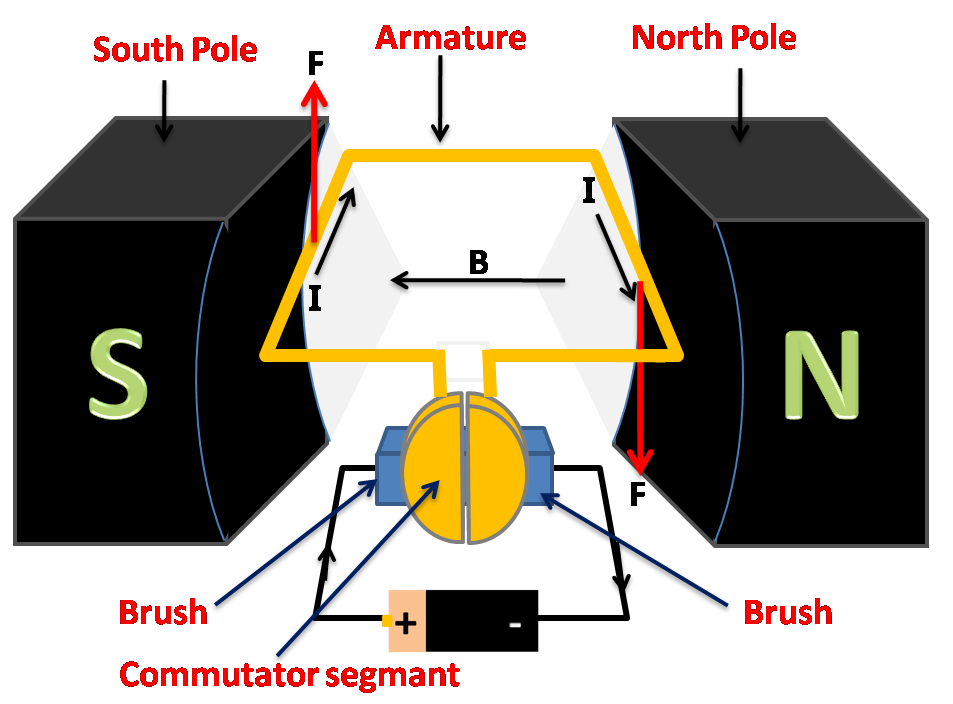
Simple Dc Motor Circuit Diagram
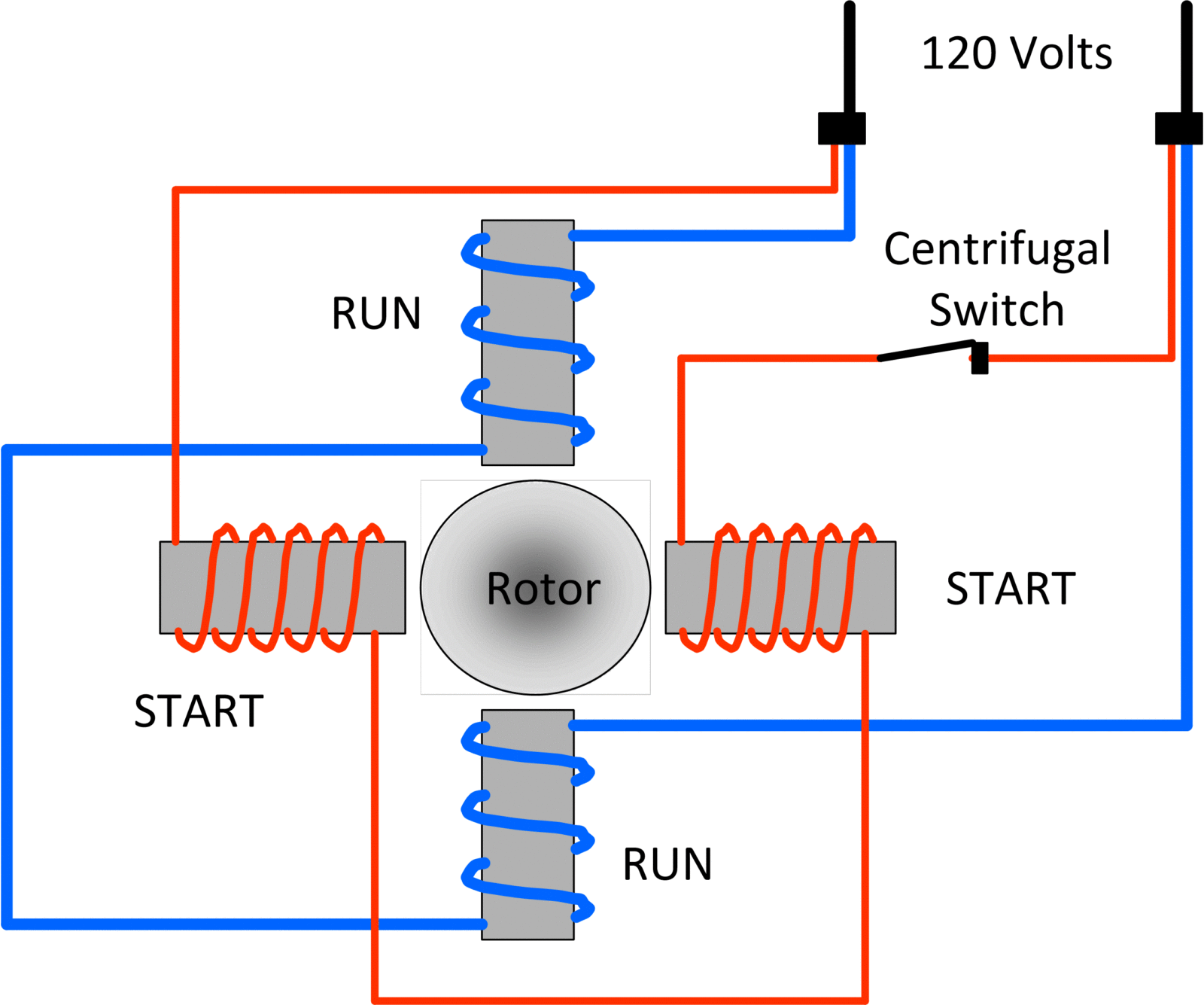
Single Phase Motor With Circuit Diagram
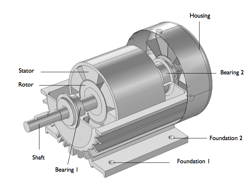
Induction Motor Schematic Diagram
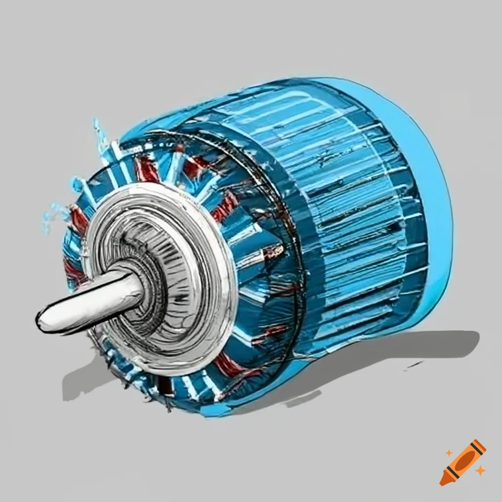
Schematic diagram of an electric motor
An Electric Motor Is A Machine That Converts Electrical Energy To Mechanical Energy.
Web Three Phase Motor Connection Schematic, Power And Control Wiring Installation Diagrams.
Web Motor Control Circuits Are Often Connected To Lower Voltages Than The Motor They Control To Make It Safer For Operators And Maintenance Personnel.
Learn How A Dc Motor Works To Understand The Basic Working Principle Of A Dc Motor.
Related Post: