Mech Drawing Symbols
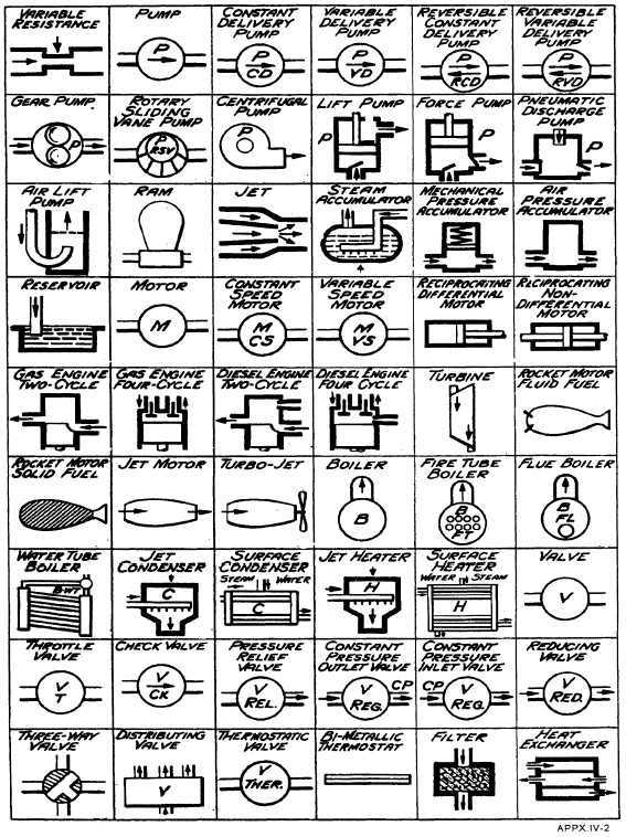
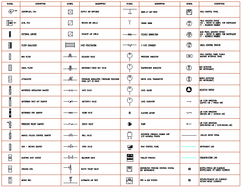
Mech Drawing Symbols - Published by gayamadhusanka on september 24, 2023. Web mechanical drawing symbols are used to represent components and processes in diagrams. Web engineering drawing abbreviations and symbols are used to communicate and detail the characteristics of an engineering drawing. An engineering (or technical) drawingis a graphical representation of a part, assembly, system, or structure and it can be produced using freehand, mechanical tools, or computer methods. Web a convenient guide for geometric dimensioning and tolerancing (gd&t) symbols at your fingertips. They are 1) piping and instrument drawings (p&ids), 2) electrical single lines and schematics, 3) electronic diagrams and schematics, 4) logic diagrams and prints, and 5) fabrication, construction, and architectural drawings. You can also check out the gd&t symbols and terms on our site. The basic symbol for the pump is a circle containing one or more arrow heads indicating the direction(s) of flow with the points of the arrows in contact with the circle. Web graphics communications are used in every phase of engineering design starting from concept illustration all the way to the manufacturing phase. Here are more commonly used engineering drawing symbols and design elements as below. Web various symbols and abbreviations in engineering drawings give you information about the dimensions, design, and materials used. Web engineering drawing abbreviations and symbols are used to communicate and detail the characteristics of an engineering drawing. [1] these symbols and abbreviations are standardized by the american national standards institute (asmi) and the american society of mechanical engineers (asme) in the. You can also check out the gd&t symbols and terms on our site. Web free courses learn how to read mechanical engineering schematic drawings. They are 1) piping and instrument drawings (p&ids), 2) electrical single lines and schematics, 3) electronic diagrams and schematics, 4) logic diagrams and prints, and 5) fabrication, construction, and architectural drawings. Web in the broad area. Design variables standard mounting heights mounting heights custom mounting heights (applies to other devices not shown here) symbol description mech. Web basic types of symbols used in engineering drawings are countersink, counterbore, spotface, depth, radius, and diameter. Currently, we have 16 symbols for geometric tolerances, which are categorized according to the tolerance they specify. These icons are essential for creating. Classification and symbols of geometric tolerance characteristics. We offer you our tips which we believe are useful for dispelling uncertainty by comparing the symbol with its graphic representation. Web find common gd&t symbols in convenient charts broken down by their use in drawing and drafting. Web engineering drawing abbreviations are a set of standardized symbols and abbreviations used on engineering. Classification and symbols of geometric tolerance characteristics. Web in the broad area of fluid power, two categories of pump symbols are used, depending on the motive media being used (i.e., hydraulic or pneumatic). Learn the symbols, the important information, how to read it and where we use them. Click on the links below to learn more about each gd&t symbol. Web engineering drawing abbreviations are a set of standardized symbols and abbreviations used on engineering drawings to represent common terms and phrases. Web various symbols and abbreviations in engineering drawings give you information about the dimensions, design, and materials used. There's a huge variety of symbols, depending on industry and manufacturer, so we've created this guide to feature the most. Lines are typically used for connecting different objects or parts of a diagram together, while boxes are used to show the size and shape of objects. Web in the broad area of fluid power, two categories of pump symbols are used, depending on the motive media being used (i.e., hydraulic or pneumatic). The symbols and abbreviations represent various components, processes,. They are 1) piping and instrument drawings (p&ids), 2) electrical single lines and schematics, 3) electronic diagrams and schematics, 4) logic diagrams and prints, and 5) fabrication, construction, and architectural drawings. Web in the broad area of fluid power, two categories of pump symbols are used, depending on the motive media being used (i.e., hydraulic or pneumatic). Web this chapter. They are 1) piping and instrument drawings (p&ids), 2) electrical single lines and schematics, 3) electronic diagrams and schematics, 4) logic diagrams and prints, and 5) fabrication, construction, and architectural drawings. These symbols can include lines, boxes, circles, arcs and text. Gd and t is stands for geometric dimensions and tolerances. Web various symbols and abbreviations in engineering drawings give. Lines are typically used for connecting different objects or parts of a diagram together, while boxes are used to show the size and shape of objects. Web basic types of symbols used in engineering drawings are countersink, counterbore, spotface, depth, radius, and diameter. Web engineering drawing abbreviations are a set of standardized symbols and abbreviations used on engineering drawings to. Web engineering drawing abbreviations and symbols are used to communicate and detail the characteristics of an engineering drawing. These symbols can include lines, boxes, circles, arcs and text. Currently, we have 16 symbols for geometric tolerances, which are categorized according to the tolerance they specify. We offer you our tips which we believe are useful for dispelling uncertainty by comparing the symbol with its graphic representation. This list includes abbreviations common to the vocabulary of people who work with engineering drawings in the manufacture and inspection of parts and assemblies. Web various symbols and abbreviations in engineering drawings give you information about the dimensions, design, and materials used. These icons are essential for creating an accurate visual language. An engineering (or technical) drawingis a graphical representation of a part, assembly, system, or structure and it can be produced using freehand, mechanical tools, or computer methods. Web basic types of symbols used in engineering drawings are countersink, counterbore, spotface, depth, radius, and diameter. The representation of the object in figure 2 is called an isometric drawing. Web this chapter will introduce the five common categories of drawings. Like other specialized diagrams, p&id's are comprised of standard shapes and symbols. There's a huge variety of symbols, depending on industry and manufacturer, so we've created this guide to feature the most popular p&id symbols supported within our p&id software and is standardized for best practice across the. Web gd&t symbols for engineering drawings | mechheart. Web graphics communications are used in every phase of engineering design starting from concept illustration all the way to the manufacturing phase. Web the asme y14.5 standard establishes symbols, definitions, and rules for geometric dimensioning and tolerancing.M&e Drawing Symbols Back To Basics Komseq

Mechanical symbols for Isometric drawings Mechanical Symbols

Mechanical Drawing Symbols Electrical Schematic Sy Bol For Machine

how to read mechanical engineering drawing symbols Wiring Work

Machining Drawing Symbols Chart Machinist Blueprint Symbols Chart

Mechanical Drawing Symbols

Appendix IV General Mechanical SymbolsCont.

Mechanical Drawing Symbols
Mechanical Engineering Drawing Symbols Pdf Free Download at

Mechanical Engineering Drawing Symbols Pdf Free Download at
Web In The Broad Area Of Fluid Power, Two Categories Of Pump Symbols Are Used, Depending On The Motive Media Being Used (I.e., Hydraulic Or Pneumatic).
The Symbols And Abbreviations Represent Various Components, Processes, And Measurements Used In Engineering Design.
Most Of The Engineering Fields Are Using Different Types Of Symbols.
Lines Are Typically Used For Connecting Different Objects Or Parts Of A Diagram Together, While Boxes Are Used To Show The Size And Shape Of Objects.
Related Post: