Hydraulic Schematic Symbols Chart
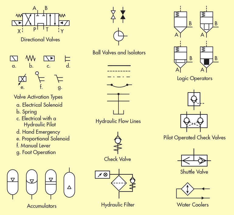
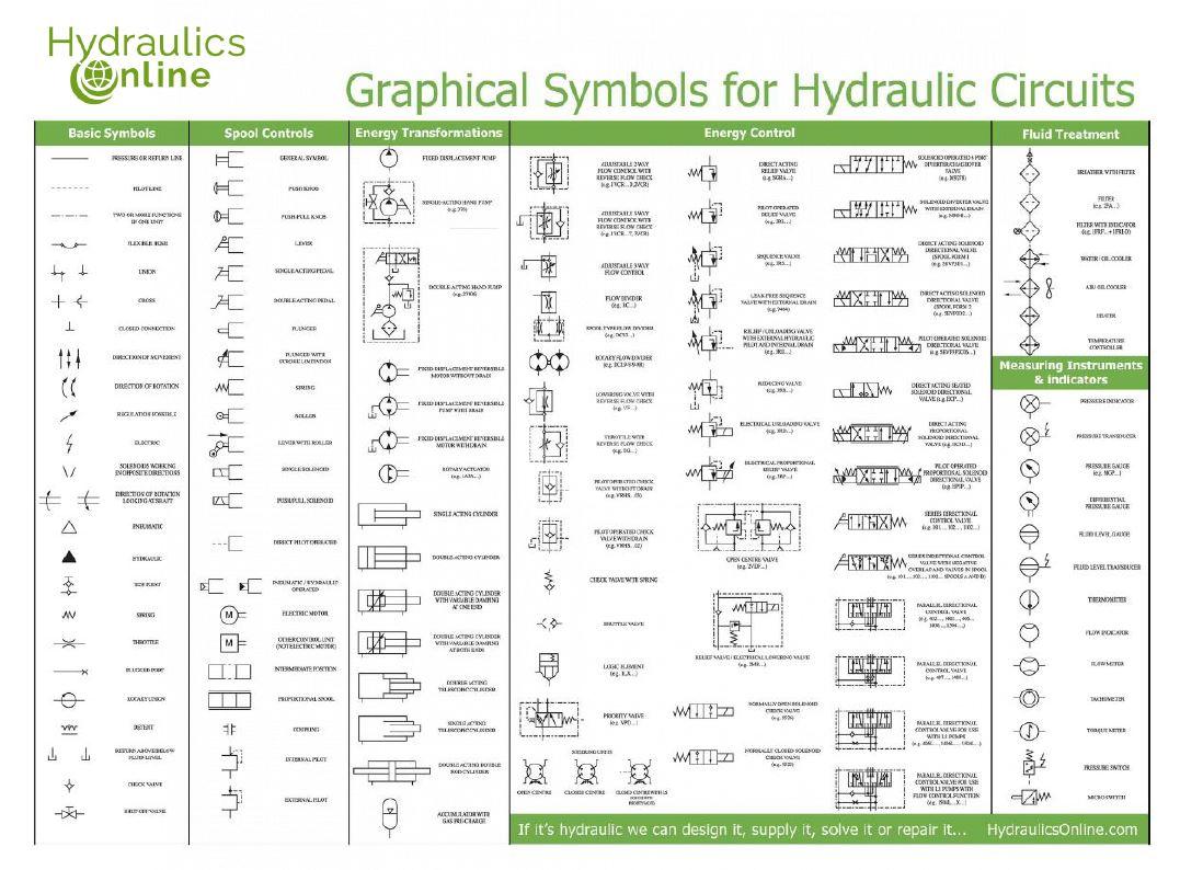
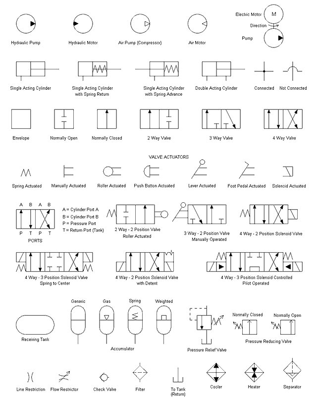
Hydraulic Schematic Symbols Chart - The basic steps to reading a hydraulic schematic are: By learning these symbols, it will be possible to construct or identify most fluid power components. Not only will you discover unique symbols, but you’ll come across unique ways to use old symbols and components in a hydraulic circuit. 1.1.1pictorial symbols are very useful for showing the interconnection of components. Web there are so many symbols to identify and lines to keep track of. Identify if lines cross with or without connecting. Web types of symbols commonly used in drawing circuit diagrams for fluid power systems are pictorial, cutaway, and graphic. Web basic symbols pressure or return line pilot line two or more functions in one unit flexible hose union closed conneci'ion direction of movement. 3rr.) electrical unloading valve (eg.3rd.) electrical proportional relief valve These symbols are fully explained in the usa standard drafting manual (ref. Web types of symbols commonly used in drawing circuit diagrams for fluid power systems are pictorial, cutaway, and graphic. Web the chart below shows many of the symbols (letters) in the language of fluid power. By learning these symbols, it will be possible to construct or identify most fluid power components. Engineers can use this page as a reference to. The basic steps to reading a hydraulic schematic are: Web i recommend you spend time reading hydraulic schematics to interpret the symbols, whenever you have time. I hope to impart to you a systematic approach to reading a hydraulic schematic. Web on this page, carr lane roemheld provides a comprehensive table outlining the definitions of each symbol used in a. 3rr.) electrical unloading valve (eg.3rd.) electrical proportional relief valve Web understanding hydraulic schematic symbols allows technicians and engineers to read and interpret hydraulic circuit diagrams accurately. I hope to impart to you a systematic approach to reading a hydraulic schematic. Web i recommend you spend time reading hydraulic schematics to interpret the symbols, whenever you have time. 1.1.1pictorial symbols are. Identify if lines cross with or without connecting. Not only will you discover unique symbols, but you’ll come across unique ways to use old symbols and components in a hydraulic circuit. These symbols are fully explained in the usa standard drafting manual (ref. For example, the seven symbols below can be rearranged in several ways to describe very different components.. Web basic symbols pressure or return line pilot line two or more functions in one unit flexible hose union closed conneci'ion direction of movement. Armed with knowledge of how basic hydraulic components are represented in the hydraulic circuit; These symbols are fully explained in the usa standard drafting manual (ref. 1.1.1pictorial symbols are very useful for showing the interconnection of. Web there are so many symbols to identify and lines to keep track of. Engineers can use this page as a reference to determine common schematic symbols used in fluid power, hydraulics, pneumatics, diagrams and circuits. Web the symbols do not identify component size or their actual position on the machine, however the symbols do provide vital information relating to. Web basic symbols pressure or return line pilot line two or more functions in one unit flexible hose union closed conneci'ion direction of movement. Armed with knowledge of how basic hydraulic components are represented in the hydraulic circuit; I hope to impart to you a systematic approach to reading a hydraulic schematic. Not only will you discover unique symbols, but. Web on this page, carr lane roemheld provides a comprehensive table outlining the definitions of each symbol used in a hydraulic diagram. Web the symbols do not identify component size or their actual position on the machine, however the symbols do provide vital information relating to the configurations and flow path connections. I hope to impart to you a systematic. Web understanding hydraulic schematic symbols allows technicians and engineers to read and interpret hydraulic circuit diagrams accurately. Not only will you discover unique symbols, but you’ll come across unique ways to use old symbols and components in a hydraulic circuit. Engineers can use this page as a reference to determine common schematic symbols used in fluid power, hydraulics, pneumatics, diagrams. Web the chart below shows many of the symbols (letters) in the language of fluid power. For example, the seven symbols below can be rearranged in several ways to describe very different components. Armed with knowledge of how basic hydraulic components are represented in the hydraulic circuit; Not only will you discover unique symbols, but you’ll come across unique ways. With external hydraulic pilot and internal drain (e.g.3rd.) reducing valve (cc. Web types of symbols commonly used in drawing circuit diagrams for fluid power systems are pictorial, cutaway, and graphic. Web i recommend you spend time reading hydraulic schematics to interpret the symbols, whenever you have time. Web there are so many symbols to identify and lines to keep track of. Not only will you discover unique symbols, but you’ll come across unique ways to use old symbols and components in a hydraulic circuit. By learning these symbols, it will be possible to construct or identify most fluid power components. For example, the seven symbols below can be rearranged in several ways to describe very different components. 3rr.) electrical unloading valve (eg.3rd.) electrical proportional relief valve Web this pdf contains the symbols and explanations for the different types of hydraulic line as well as some basic components you may encounter when reading or creating a hydraulic circuit diagram. This knowledge is crucial for troubleshooting, maintenance, and designing hydraulic systems, ensuring their optimal performance and efficiency. I hope to impart to you a systematic approach to reading a hydraulic schematic. These symbols are fully explained in the usa standard drafting manual (ref. One can understand a wide range of different hydraulic symbols, representing components performing similar tasks with. Web basic symbols pressure or return line pilot line two or more functions in one unit flexible hose union closed conneci'ion direction of movement. Engineers can use this page as a reference to determine common schematic symbols used in fluid power, hydraulics, pneumatics, diagrams and circuits. Web on this page, carr lane roemheld provides a comprehensive table outlining the definitions of each symbol used in a hydraulic diagram.
A guide to common hydraulic symbols EngineeringClicks

What’s the Difference Between Hydraulic Circuit Symbols? Machine Design

Hydraulic Symbols And Schematics

Electrical, Hydraulic and Pneumatic Diagram Software

Hydraulic Flow Schematic Symbols

How To Draw Hydraulic Schematics

Hydraulic Schematic Symbols
Hydraulic Symbols

Hydraulic Schematic Drawing Symbols Wiring Diagram
Hydraulic Symbols Valve Machines
1.1.1Pictorial Symbols Are Very Useful For Showing The Interconnection Of Components.
Web Understanding Hydraulic Schematic Symbols Allows Technicians And Engineers To Read And Interpret Hydraulic Circuit Diagrams Accurately.
Web The Symbols Do Not Identify Component Size Or Their Actual Position On The Machine, However The Symbols Do Provide Vital Information Relating To The Configurations And Flow Path Connections.
Armed With Knowledge Of How Basic Hydraulic Components Are Represented In The Hydraulic Circuit;
Related Post:

