Glulam Beam Span Chart
Glulam Beam Span Chart - • table values assume that lateral support is provided at each support and continuously along the compression edge of the beam. Web tables 2, 3, 8 and 9 provide allowable loads for glulam beams used as simple span roof members for non‑snow loads (dol factor = 1.25) and in snow load areas (dol factor = 1.15). Web tables 2, 3, 8 and 9 provide allowable loads for glulam beams used as simple span roof members for non‑snow loads (dol factor = 1.25) and in snow load areas (dol factor = 1.15). Total load deflection limit = span/240. As per thumb rule & general guideline, depth of the glulam beam is 1/20th of span in inches and their width is 1/3 to 1/4 of the depth. Live load ≤ 0.67 x total load. Rule of thumb for sizing glulam beam: • table values for minimum required bearing lengths are based on the allowable compression design value perpendicular to grain for the beam and the load value Web a glulam span calculator is a digital tool that helps determine the maximum length a glulam beam can span in a construction project, based on the load it needs to support and other factors, ensuring safety and structural integrity. Full lateral support on the compression side. • table values assume that lateral support is provided at each support and continuously along the compression edge of the beam. As per thumb rule & general guideline, depth of the glulam beam is 1/20th of span in inches and their width is 1/3 to 1/4 of the depth. Web tables 2, 3, 8 and 9 provide allowable loads for. Web a glulam span calculator is a digital tool that helps determine the maximum length a glulam beam can span in a construction project, based on the load it needs to support and other factors, ensuring safety and structural integrity. V8 boise glulam® beams may be special ordered at an additional cost; Web glulam beam size calculator. Live load ≤. Web a glulam span calculator is a digital tool that helps determine the maximum length a glulam beam can span in a construction project, based on the load it needs to support and other factors, ensuring safety and structural integrity. Check with your local distributor for availability. • table values for minimum required bearing lengths are based on the allowable. Live load ≤ 0.67 x total load. V8 boise glulam® beams may be special ordered at an additional cost; Web glulam beam size calculator. Web • span is measured center to center of the supports. To facilitate installation, all top sides of unbalanced layups are identified with a stamp to designate orientation. • table values for minimum required bearing lengths are based on the allowable compression design value perpendicular to grain for the beam and the load value Full lateral support on the compression side. Web glulam beam size calculator. Live load ≤ 0.67 x total load. To facilitate installation, all top sides of unbalanced layups are identified with a stamp to. V8 boise glulam® beams may be special ordered at an additional cost; Web tables 2, 3, 8 and 9 provide allowable loads for glulam beams used as simple span roof members for non‑snow loads (dol factor = 1.25) and in snow load areas (dol factor = 1.15). Web glulam beam size calculator. Rule of thumb for sizing glulam beam: To. Live load ≤ 0.67 x total load. Check with your local distributor for availability. Web a glulam span calculator is a digital tool that helps determine the maximum length a glulam beam can span in a construction project, based on the load it needs to support and other factors, ensuring safety and structural integrity. • table values assume that lateral. V8 boise glulam® beams may be special ordered at an additional cost; Web glulam beam size calculator. Live load ≤ 0.67 x total load. Total load deflection limit = span/240. Web a glulam span calculator is a digital tool that helps determine the maximum length a glulam beam can span in a construction project, based on the load it needs. Web tables 2, 3, 8 and 9 provide allowable loads for glulam beams used as simple span roof members for non‑snow loads (dol factor = 1.25) and in snow load areas (dol factor = 1.15). Live load ≤ 0.67 x total load. Web a glulam span calculator is a digital tool that helps determine the maximum length a glulam beam. Web • span is measured center to center of the supports. • table values assume that lateral support is provided at each support and continuously along the compression edge of the beam. As per thumb rule & general guideline, depth of the glulam beam is 1/20th of span in inches and their width is 1/3 to 1/4 of the depth.. Web glulam beam size calculator. As per thumb rule & general guideline, depth of the glulam beam is 1/20th of span in inches and their width is 1/3 to 1/4 of the depth. Web • span is measured center to center of the supports. Check with your local distributor for availability. Full lateral support on the compression side. Rule of thumb for sizing glulam beam: To facilitate installation, all top sides of unbalanced layups are identified with a stamp to designate orientation. Web a glulam span calculator is a digital tool that helps determine the maximum length a glulam beam can span in a construction project, based on the load it needs to support and other factors, ensuring safety and structural integrity. Live load ≤ 0.67 x total load. Web tables 2, 3, 8 and 9 provide allowable loads for glulam beams used as simple span roof members for non‑snow loads (dol factor = 1.25) and in snow load areas (dol factor = 1.15). V8 boise glulam® beams may be special ordered at an additional cost; Web tables 2, 3, 8 and 9 provide allowable loads for glulam beams used as simple span roof members for non‑snow loads (dol factor = 1.25) and in snow load areas (dol factor = 1.15).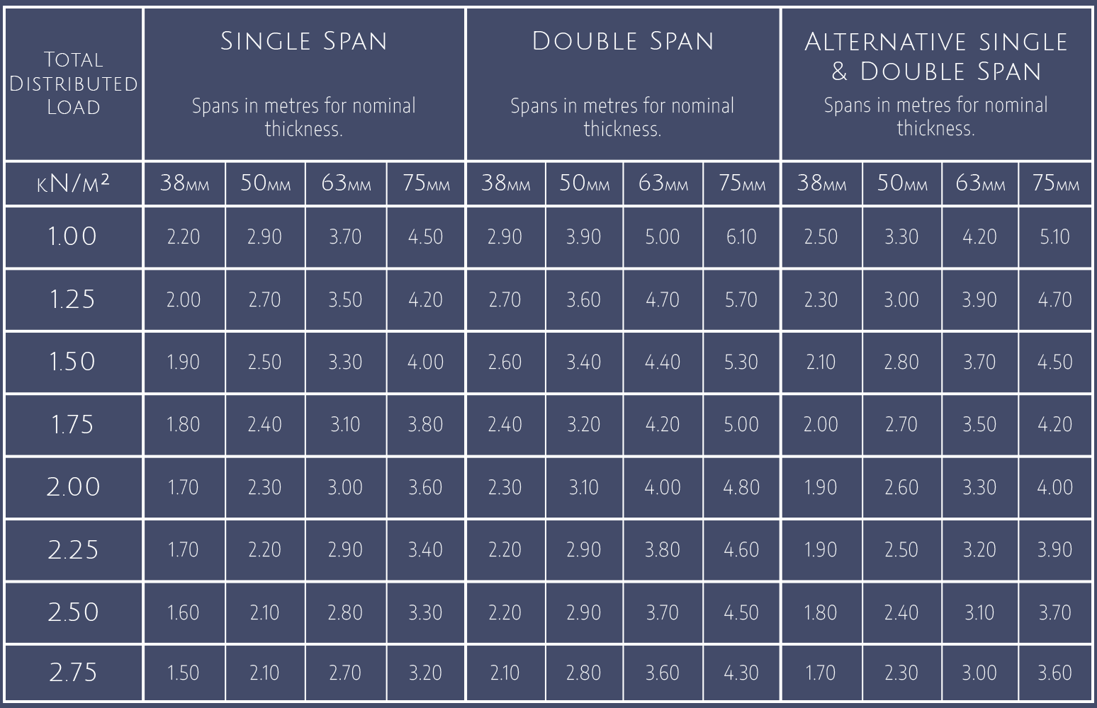
Solid Timber Decking Specifications Glulam Ltd
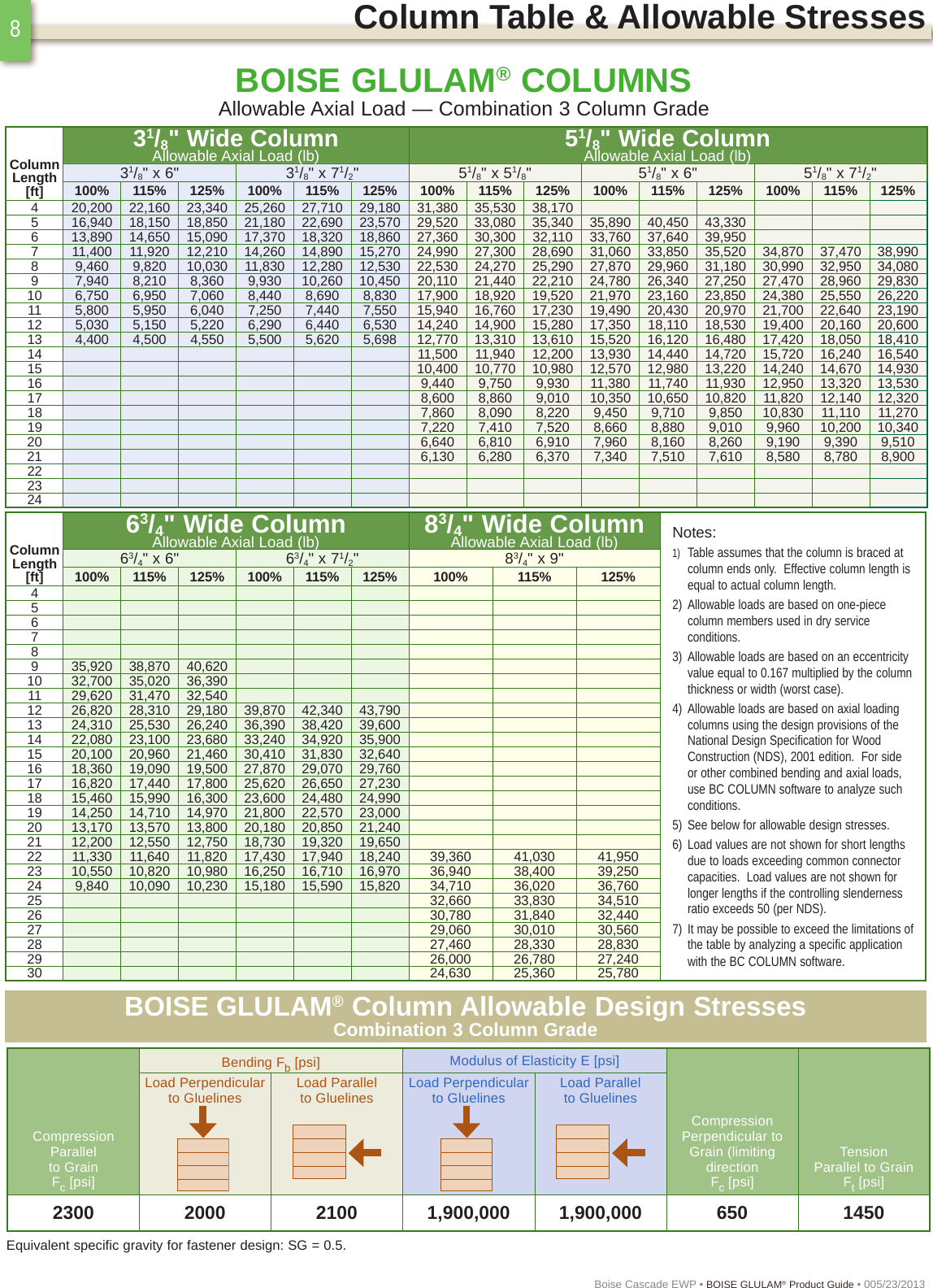
Glulam Beam Header Span Table Elcho Table

Glulam Span Chart For Beams

Glulam Beam Sizes Chart Printable Templates Free
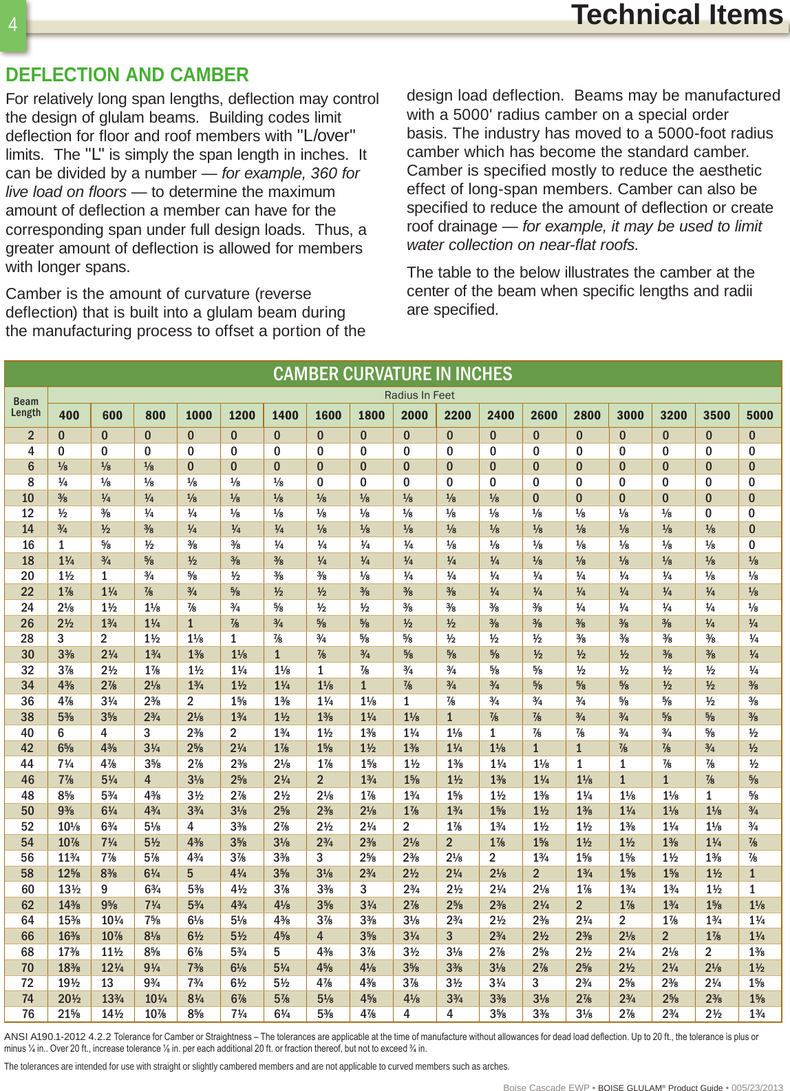
Span Glulam Beam Sizes Chart
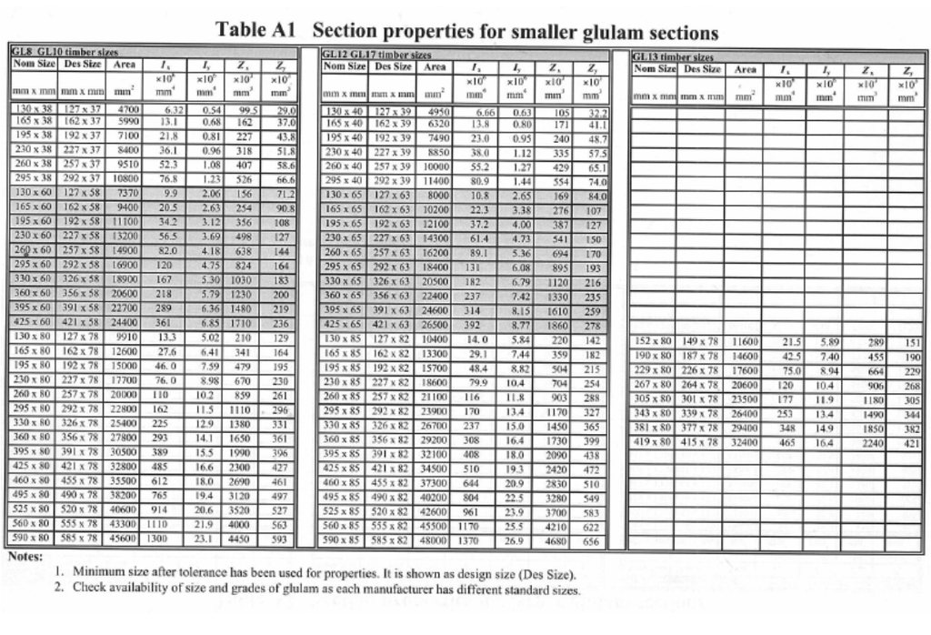
Span Glulam Beam Sizes Chart vrogue.co
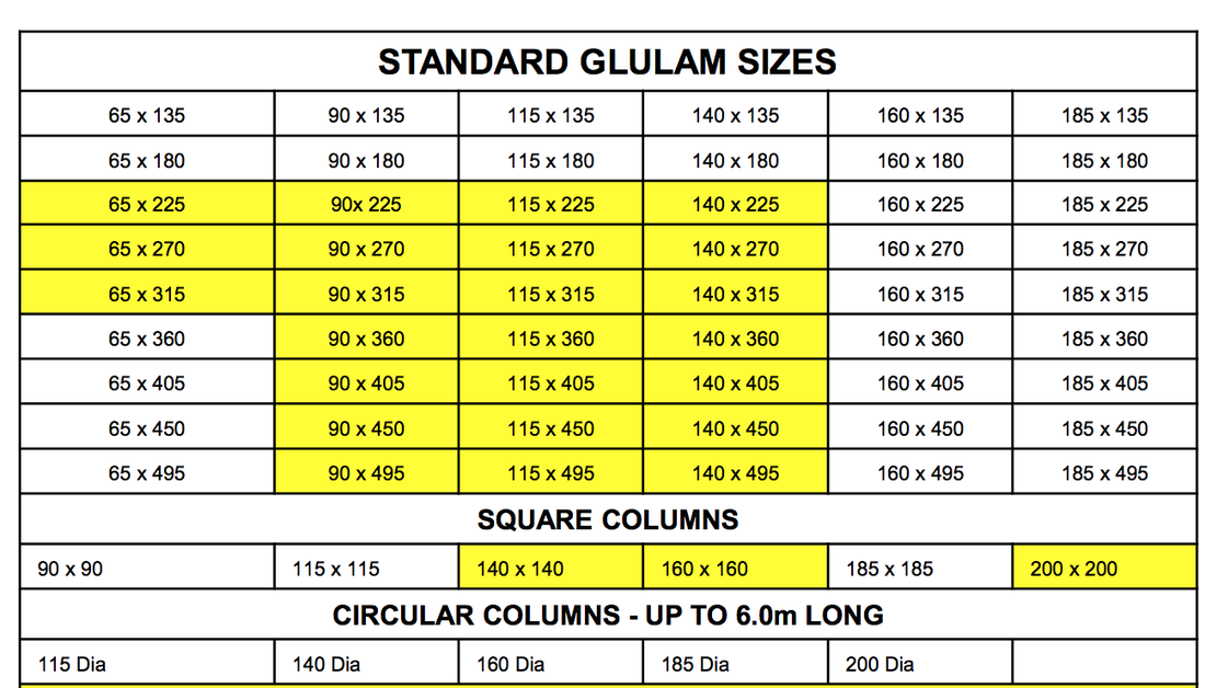
Glulam Beam Span Tables My XXX Hot Girl

Glulam Span Chart For Beams
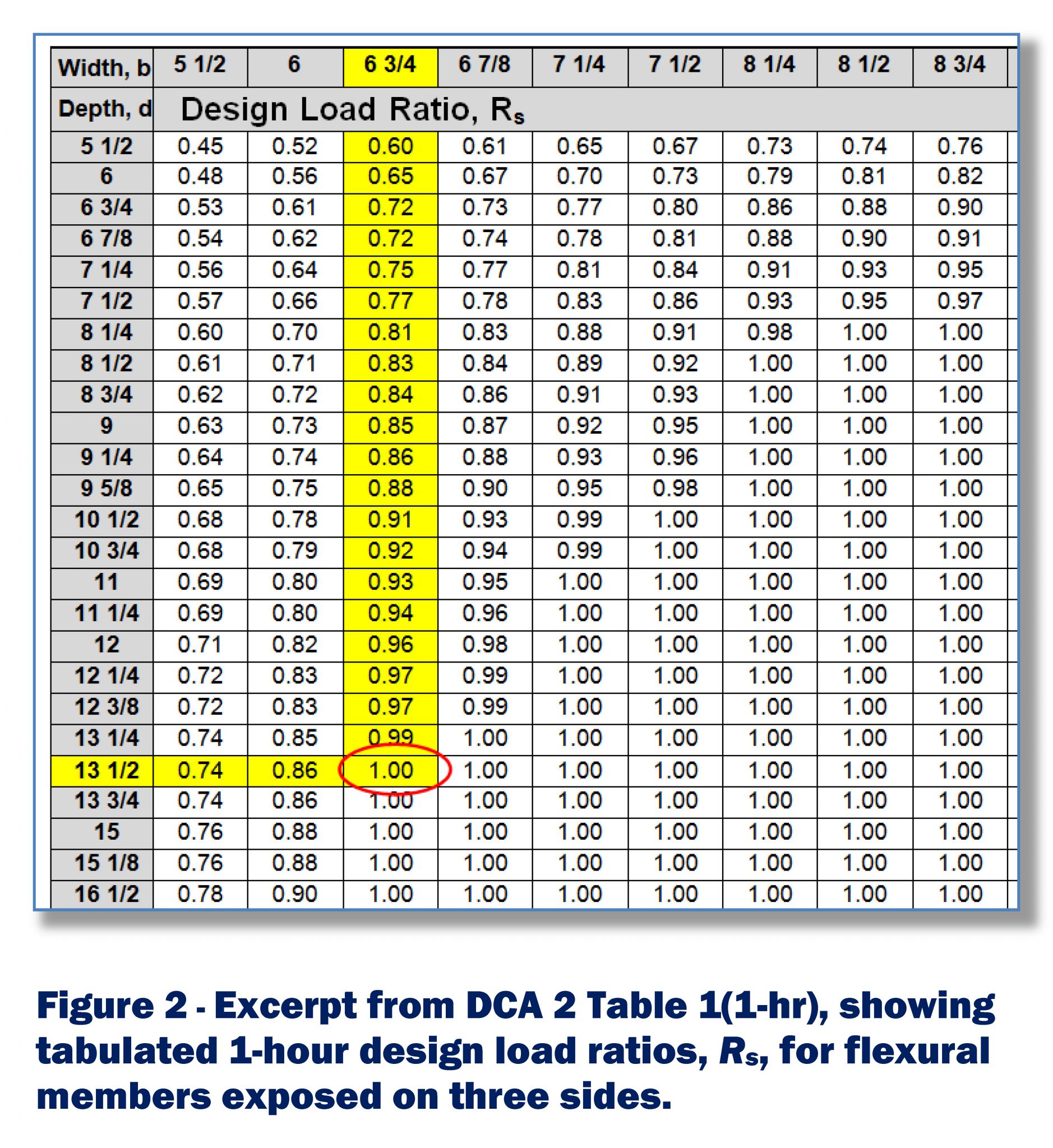
Laminated Wood Beams Span Tables
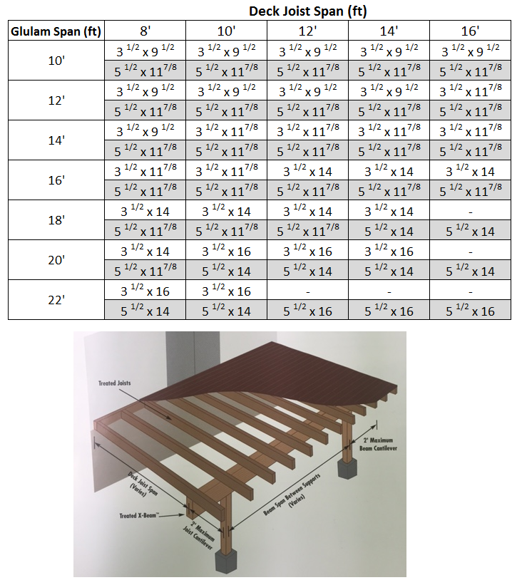
Glulam Beams
• Table Values Assume That Lateral Support Is Provided At Each Support And Continuously Along The Compression Edge Of The Beam.
• Table Values For Minimum Required Bearing Lengths Are Based On The Allowable Compression Design Value Perpendicular To Grain For The Beam And The Load Value
Total Load Deflection Limit = Span/240.
Related Post: