Engineered Drawings
Engineered Drawings - Web what is general notes in engineering drawing? Various symbols and abbreviations in engineering drawings give you information about the dimensions, design, and materials used. Some of the most important information on engineering drawings, are general notes. By understanding the purpose and conventions of each. Web the purpose of this guide is to give you the basics of engineering sketching and drawing. A common use is to specify the geometry necessary for the construction of a component and is called a detail drawing. It fully and clearly describes the requirements for engineered items. Usually, a number of drawings are necessary to completely specify even a simple component. It is more than simply a drawing, it is a graphical language that communicates ideas and information. Web read about different types of drawing projection methods, and learn about the most important ones for engineering drawing creation. We will treat “sketching” and “drawing” as one. The rules for creating engineering drawings (communication) are defined by a standards organization (for. In that way, a drawing is actually a specification that serves as a contract like agreement between a design organization and a manufacturing organization. Web the purpose of this guide is to give you the basics of engineering. Web engineering drawings are one of the most important engineering documents. Web the structural engineer, volume 102, issue 8, 2024, page(s) 47. Engineering drawings use standardised language and symbols. Learn about the main elements of the engineering drawings. The video below covers the fundamentals, including the different types of views, first and third angle projection methods, dimensioning, tolerancing, best practices. Web an engineering drawing (also named as mechanical drawing, manufacturing blueprints, drawings, dimensional prints, and more) refers to one of the technical drawings, which helps to define engineering products’ requirements. Web the purpose of this guide is to give you the basics of engineering sketching and drawing. In that way, a drawing is actually a specification that serves as a. Web the structural engineer, volume 102, issue 8, 2024, page(s) 47. Various symbols and abbreviations in engineering drawings give you information about the dimensions, design, and materials used. Web what is general notes in engineering drawing? Usually, a number of drawings are necessary to completely specify even a simple component. Web the purpose of this guide is to give you. Detail, assembly, or installation drawing, except that it presents pictorial, notational, or dimensional data to the extent necessary to convey the design solution used in preparing other engineering drawings. Web an engineering drawing is a subcategory of technical drawings. Read more » basic elements of engineering drawings Various symbols and abbreviations in engineering drawings give you information about the dimensions,. Web explore the three primary types of engineering drawings: Web what is general notes in engineering drawing? This is so easily overlooked, but may convey very important information and instructions to the person reading the drawing. Orthographic projection, isometric projection, and assembly drawings. The video below covers the fundamentals, including the different types of views, first and third angle projection. Web explore the three primary types of engineering drawings: In that way, a drawing is actually a specification that serves as a contract like agreement between a design organization and a manufacturing organization. It fully and clearly describes the requirements for engineered items. An engineering (or technical) drawingis a graphical representation of a part, assembly, system, or structure and it. Web an engineering drawing (also named as mechanical drawing, manufacturing blueprints, drawings, dimensional prints, and more) refers to one of the technical drawings, which helps to define engineering products’ requirements. Web the structural engineer, volume 102, issue 8, 2024, page(s) 47. It is more than simply a drawing, it is a graphical language that communicates ideas and information. Web the. Web the purpose of this guide is to give you the basics of engineering sketching and drawing. This is so easily overlooked, but may convey very important information and instructions to the person reading the drawing. Learn about the main elements of the engineering drawings. Web understanding engineering drawings. This month, ron has chosen a sketch by nick maerkl as. “sketching” generally means freehand drawing. A common use is to specify the geometry necessary for the construction of a component and is called a detail drawing. They are 1) piping and instrument drawings (p&ids), 2) electrical single lines and schematics, 3) electronic diagrams and schematics, 4) logic diagrams and prints, and 5) fabrication, construction, and architectural drawings. Web explore the. This list includes abbreviations common to the vocabulary of people who work with engineering drawings in the manufacture and inspection of parts and assemblies. Web engineering drawing abbreviations and symbols are used to communicate and detail the characteristics of an engineering drawing. In that way, a drawing is actually a specification that serves as a contract like agreement between a design organization and a manufacturing organization. They are 1) piping and instrument drawings (p&ids), 2) electrical single lines and schematics, 3) electronic diagrams and schematics, 4) logic diagrams and prints, and 5) fabrication, construction, and architectural drawings. Web graphics communications are used in every phase of engineering design starting from concept illustration all the way to the manufacturing phase. It is more than simply a drawing, it is a graphical language that communicates ideas and information. Web the purpose of this guide is to give you the basics of engineering sketching and drawing. Some of the most important information on engineering drawings, are general notes. Usually, a number of drawings are necessary to completely specify even a simple component. The video below covers the fundamentals, including the different types of views, first and third angle projection methods, dimensioning, tolerancing, best practices when creating drawings. Web an engineering drawing (also named as mechanical drawing, manufacturing blueprints, drawings, dimensional prints, and more) refers to one of the technical drawings, which helps to define engineering products’ requirements. “sketching” generally means freehand drawing. Web an engineering drawing is a subcategory of technical drawings that show the shape, structure, dimensions, tolerances, accuracy and other requirements needed to manufacture a product or part. The rules for creating engineering drawings (communication) are defined by a standards organization (for. This month, ron has chosen a sketch by nick maerkl as the winner of the drawing board. Web just as an architectural drawing or blueprint shows you how to construct a building, an engineering drawing shows you how to manufacture a specific item or product.
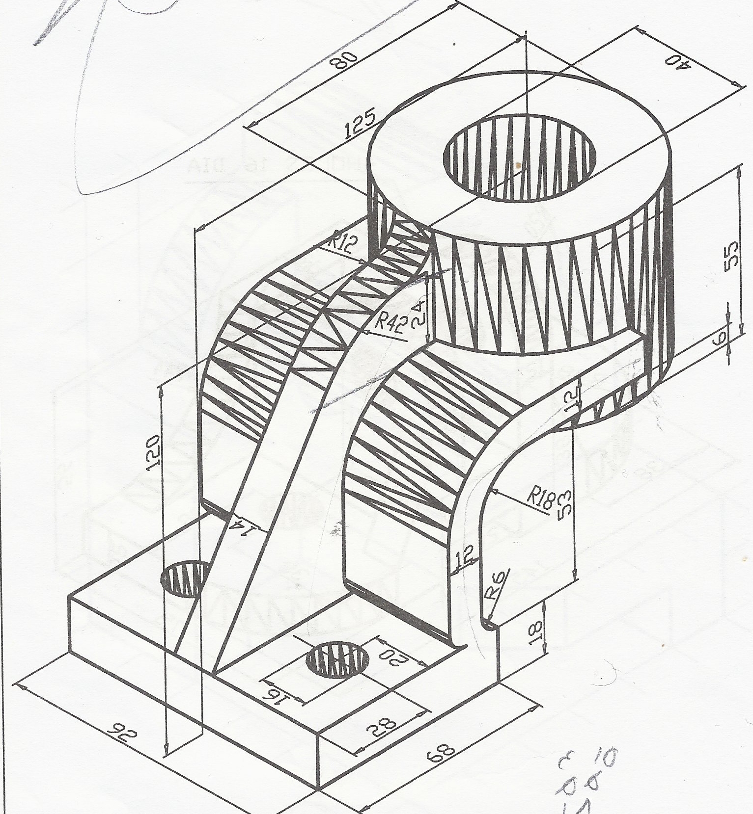
Mechanical Engineer Drawing at GetDrawings Free download
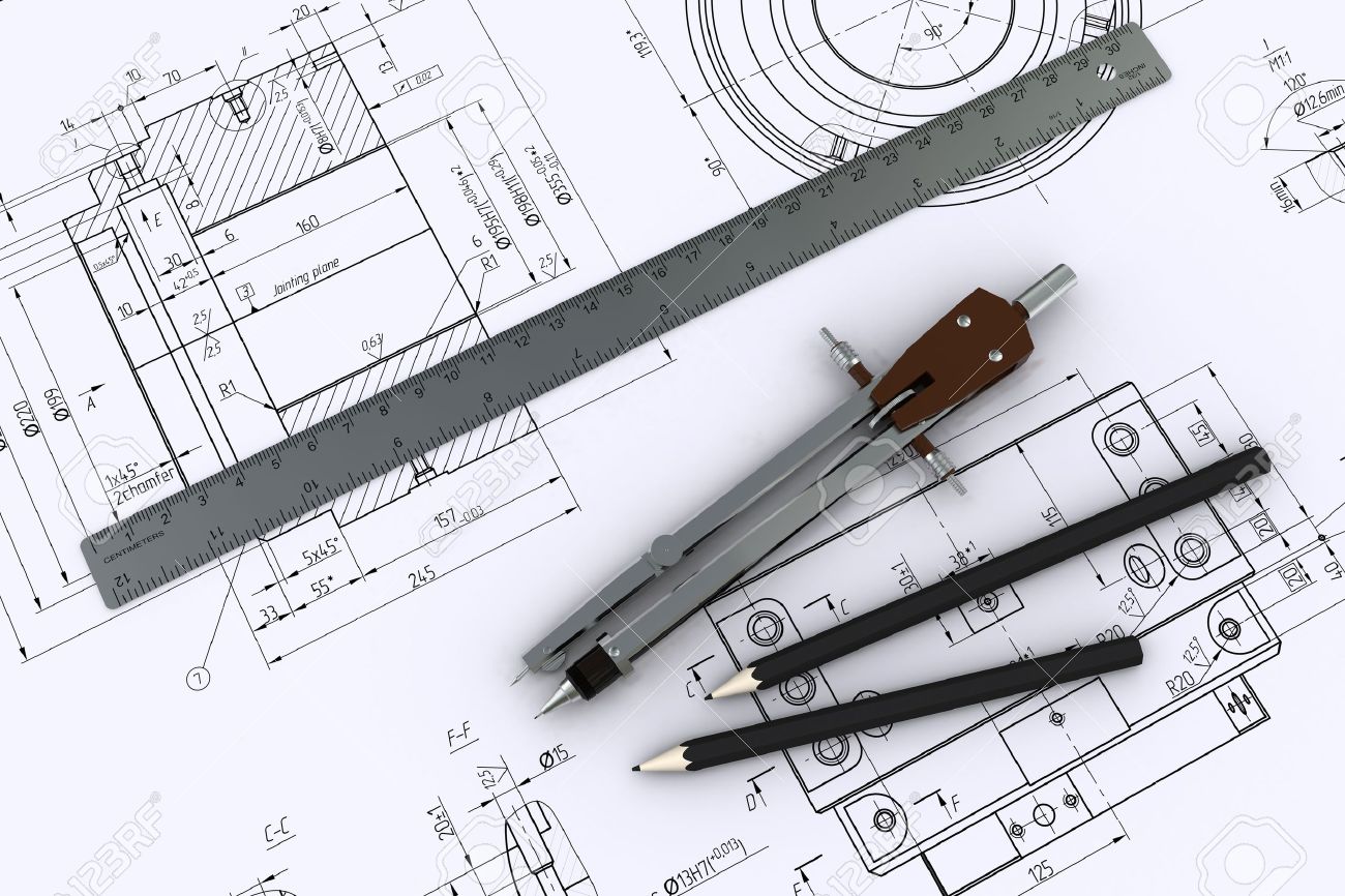
Engineering Drawing A Science or Art RRCE
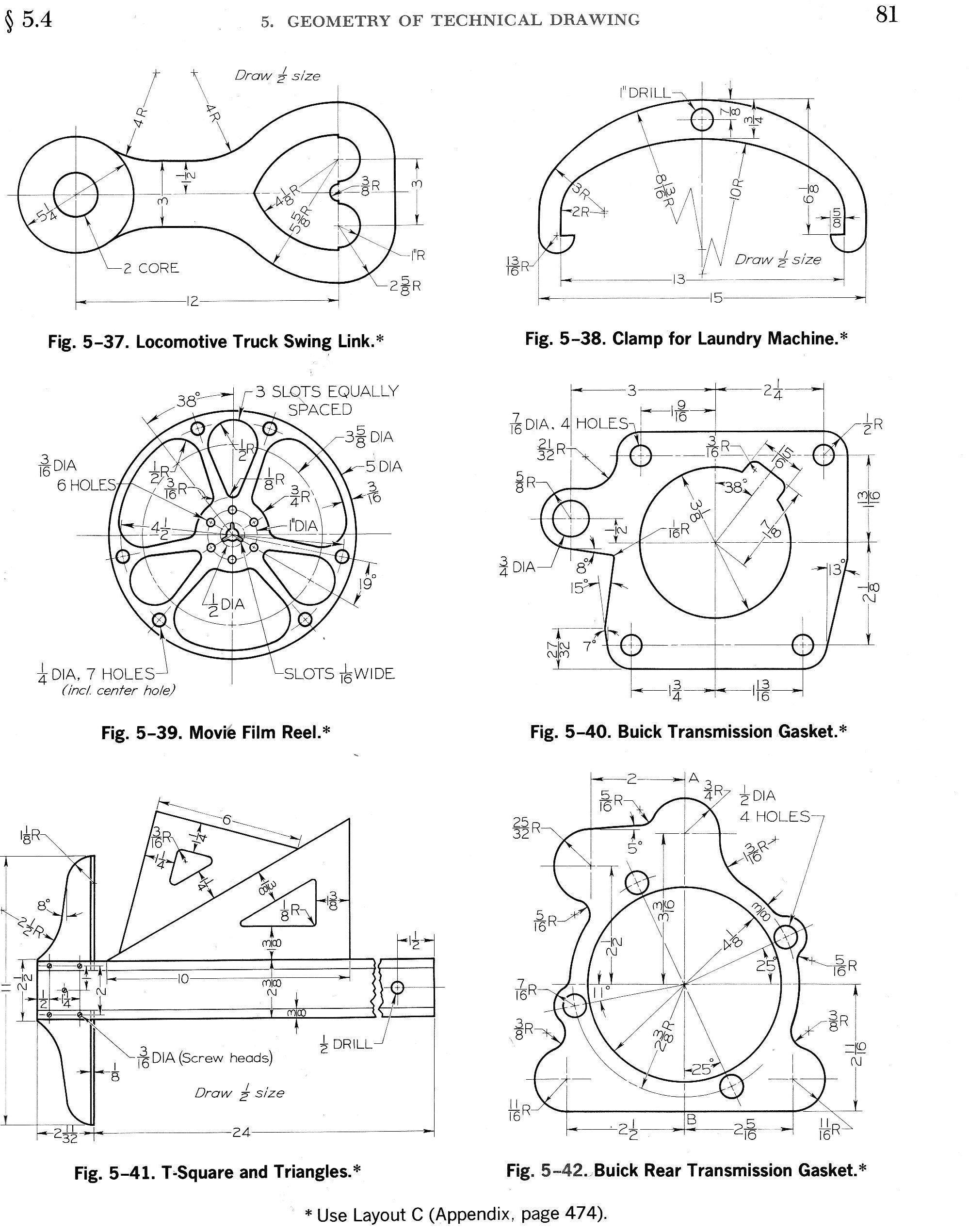
Engineering Drawing Symbols And Their Meanings Pdf at GetDrawings
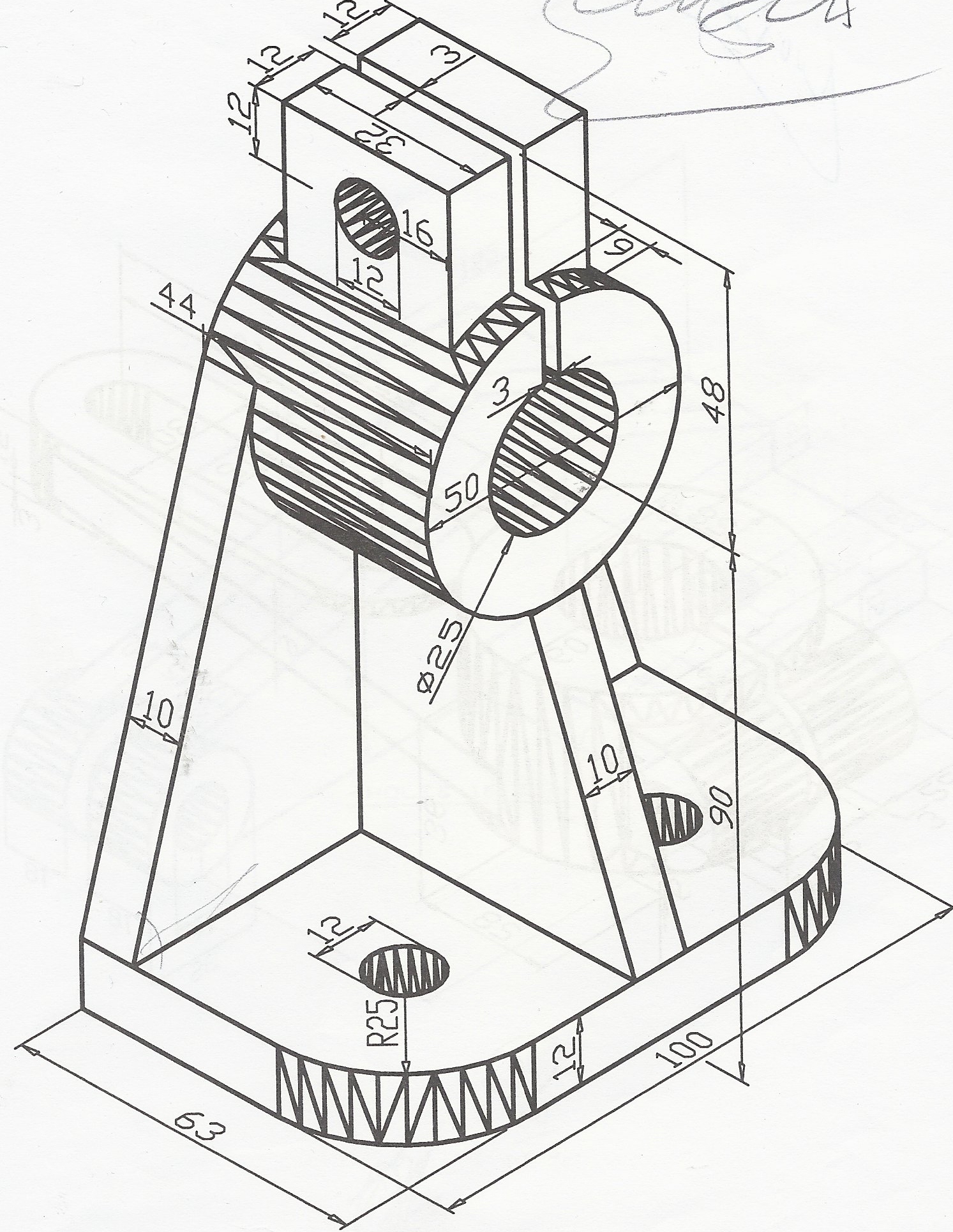
Engineering Drawing at GetDrawings Free download

how to read civil engineering drawings Engineering Feed
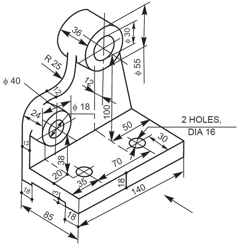
Engineering Drawing at GetDrawings Free download
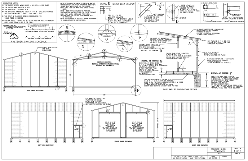
Engineered Drawings
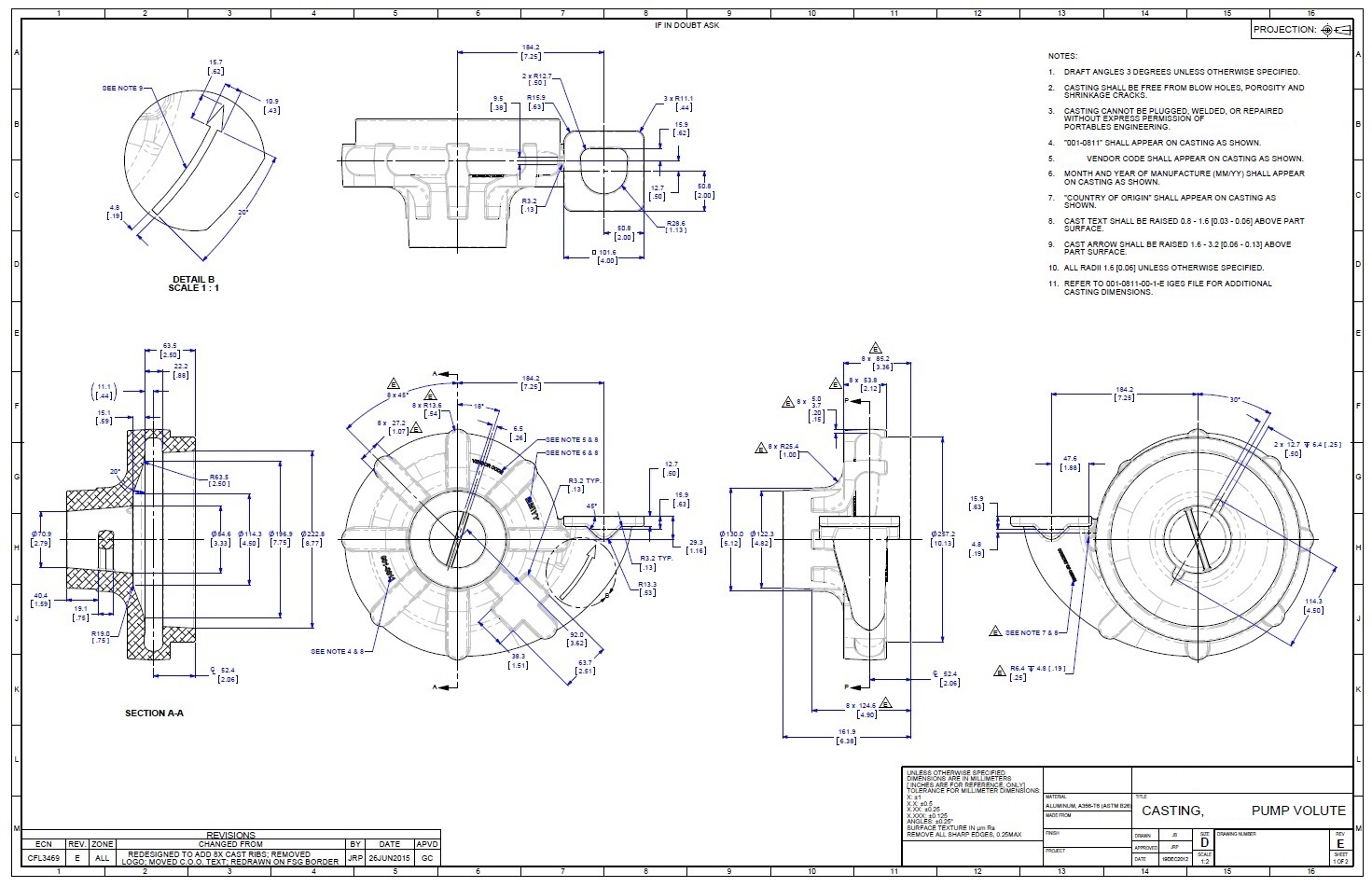
Engineering Drawings Justin R. Palmer
Mechanical Engineering Drawing at GetDrawings Free download

Engineering Drawings Justin R. Palmer
Layout Drawing Depicts Design Development Requirements.
Web Engineering Drawings Are Key Tools That Engineers Use To Communicate, But Deciphering Them Isn’t Always Straightforward.
Web Engineering By Nature.
A Common Use Is To Specify The Geometry Necessary For The Construction Of A Component And Is Called A Detail Drawing.
Related Post:
