Electrical Single Line Drawing Symbols
Electrical Single Line Drawing Symbols - Basics 8 aov elementary & block diagram : Incoming main fuses, cutouts, switches, and main/tie breakers. A single line can show all or part of a system. The schematic is commonly used in designing, operating, and maintaining electrical power systems. How is a single line calculated? Web single line diagrams are used in common engineering practice as graphical representation of electrical switchboard or assembly containing more sections, i.e. Its emphasis is on communicating the functions of the power equipment. They are used to represent and communicate the structure and connections within an electrical system in a simplified and standardized manner. Web an electrical single line diagram is a graphical representation of an electrical system’s components and connections. Web this electrical one line diagram is the primary reference for maintenance and operations for lockout/tagout procedures, as well as for any engineering power system studies. Basically, they are simplified and digest picture of whole switchboard, showing only major power equipment and connections to other switchboards, usually with addition of major. Web we usually depict the electrical distribution system by a graphic representation called a single line diagram (sld). Its emphasis is on communicating the functions of the power equipment. How is a single line calculated?. Web we usually depict the electrical distribution system by a graphic representation called a single line diagram (sld). Incoming lines showing voltage and size. Web learn about the iec symbols used in single line diagrams for electrical systems. Its emphasis is on communicating the functions of the power equipment. Sld must be started with an index, legend, page references. Web an electrical single line diagram is a graphical representation of an electrical system’s components and connections. It shows the flow of electricity through the system using a single line and standardized electrical symbols. Web we usually depict the electrical distribution system by a graphic representation called a single line diagram (sld). Web learn about the symbols used in single. A single line can show all or part of a system. It shows the flow of electricity through the system using a single line and standardized electrical symbols. Web this electrical one line diagram is the primary reference for maintenance and operations for lockout/tagout procedures, as well as for any engineering power system studies. Basics 10 480 v pump schematic. Web single line diagrams are used in common engineering practice as graphical representation of electrical switchboard or assembly containing more sections, i.e. Understand the importance of these symbols in electrical engineering and how they aid in the understanding and design of electrical systems. Web understand what is single line diagram and what are different symbols that are used in single. A single line can show all or part of a system. Its emphasis is on communicating the functions of the power equipment. A typical package of single line diagram shall include: A diagram that locates and identifies electrical devices, terminals, and interconnecting wiring in an assembly. The schematic is commonly used in designing, operating, and maintaining electrical power systems. It uses standardized symbols to depict various elements such as generators, transformers, switches, motors, and protective devices. Web single line diagrams are used in common engineering practice as graphical representation of electrical switchboard or assembly containing more sections, i.e. Of course, the symbol must also include written text showing the. They are used to represent and communicate the structure and. It uses standardized symbols to depict various elements such as generators, transformers, switches, motors, and protective devices. The schematic is commonly used in designing, operating, and maintaining electrical power systems. Also find the significance of slds in power. In this post, i will show why you need an sld and how to make it. Web learn about the iec symbols. In this post, i will show why you need an sld and how to make it. They are used to represent and communicate the structure and connections within an electrical system in a simplified and standardized manner. How is a single line calculated? Understand the importance of these symbols in electrical engineering and how they aid in the understanding and. They are used to represent and communicate the structure and connections within an electrical system in a simplified and standardized manner. Web single line diagrams are used in common engineering practice as graphical representation of electrical switchboard or assembly containing more sections, i.e. Web we usually depict the electrical distribution system by a graphic representation called a single line diagram. Incoming main fuses, cutouts, switches, and main/tie breakers. Incoming lines showing voltage and size. Web this electrical one line diagram is the primary reference for maintenance and operations for lockout/tagout procedures, as well as for any engineering power system studies. Understand the meaning and representation of each symbol, and how they are used in schematic drawings for power distribution and control systems. A single line can show all or part of a system. Also find the significance of slds in power. Web the single line diagram (sld) is the most basic of the set of diagrams that are used to document the electrical functionality of the substation. Web learn about the iec symbols used in single line diagrams for electrical systems. It shows the flow of electricity through the system using a single line and standardized electrical symbols. Its emphasis is on communicating the functions of the power equipment. It uses standardized symbols to depict various elements such as generators, transformers, switches, motors, and protective devices. Web we usually depict the electrical distribution system by a graphic representation called a single line diagram (sld). In this post, i will show why you need an sld and how to make it. All proper symbols shall be used. Of course, the symbol must also include written text showing the. Basically, they are simplified and digest picture of whole switchboard, showing only major power equipment and connections to other switchboards, usually with addition of major.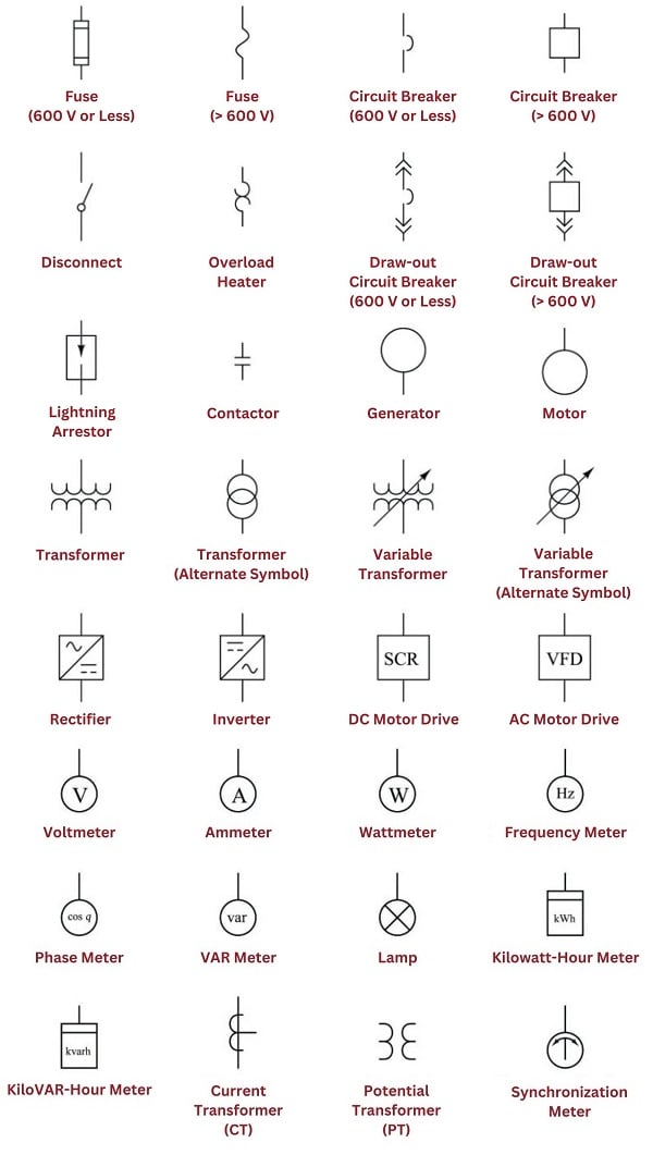
Singleline Electrical Diagrams Electric Power Measurement and

Electrical Single Line Diagram Symbols
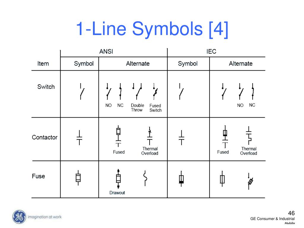
Electrical Single Line Diagram Symbols
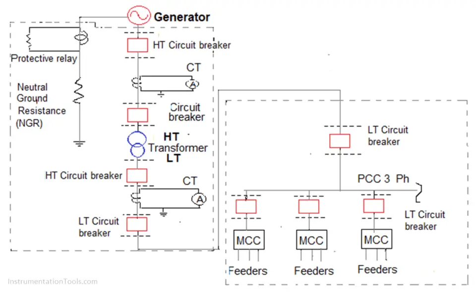
How to Read and Understand an Electrical Single Line Diagram?
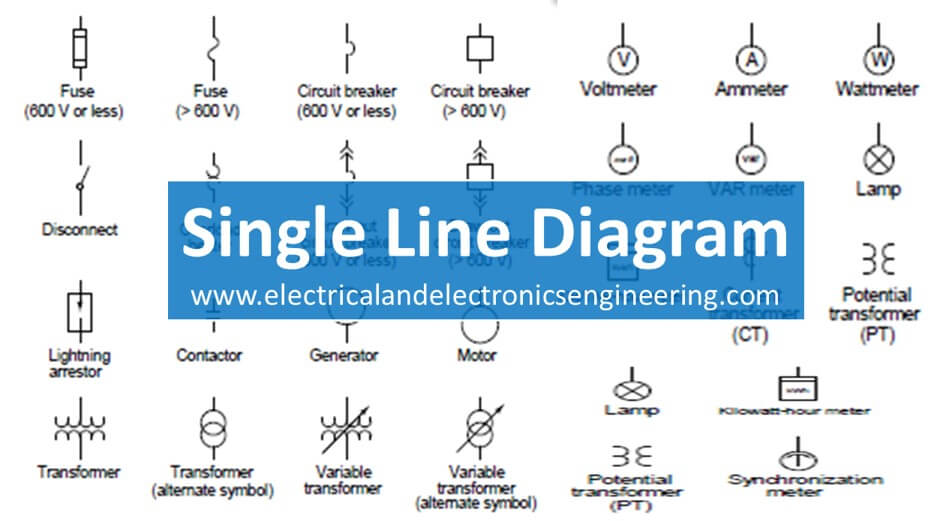
20 Single Line Diagram Symbols you need to know Electrical and
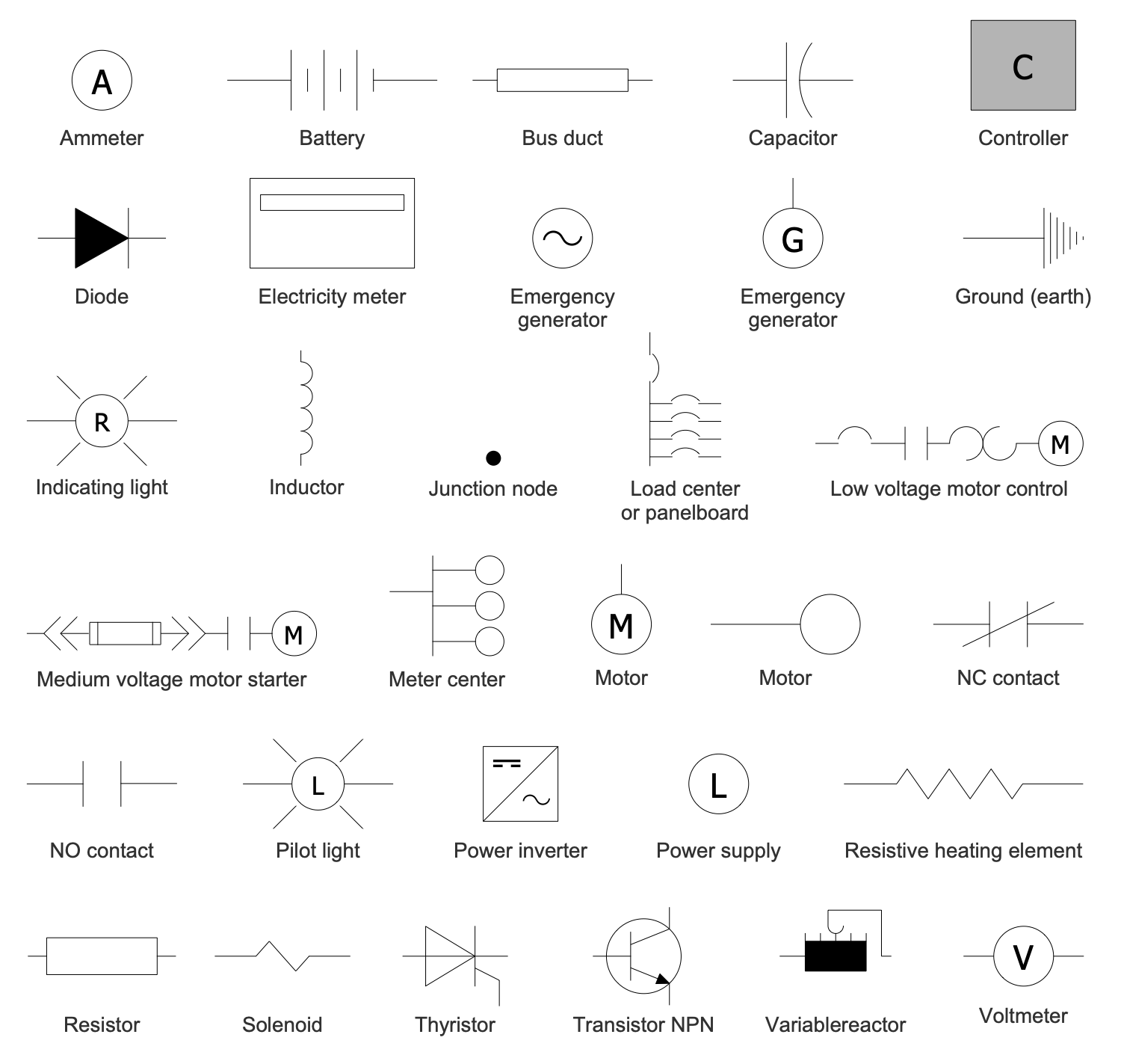
Oneline Diagrams Solution

ELECTRICAL LEGEND SINGLE LINE & SCHEMATIC SYMBOLS CAD Block And

Electrical Single Line Diagrams Circuit Symbols

How To Calculate and Draw a Single Line Diagram For The Power System EEP

What Is a Single Line Diagram & How to Draw a Circuit Diagram
Web An Electrical Single Line Diagram Is A Graphical Representation Of An Electrical System’s Components And Connections.
How Is A Single Line Calculated?
Basics 10 480 V Pump Schematic :
The Schematic Is Commonly Used In Designing, Operating, And Maintaining Electrical Power Systems.
Related Post: