Drawing Valve
Drawing Valve - The valves which are mainly used to regulate the flow of fluid in hydraulic circuits are known as “flow control valves”. Web type of valve employed depends on nature of fluid, flow control required, operating pressure and temperatures as well as surround atmosphere. Web learn about valves symbols used in p&id and piping isometric drawings. Web the complex world of process and instrumentation drawings (p&ids) is replete with a range of valve diagrams and symbols. This category includes rotameters, orifices,. Symboles for gate, globe, check, plug, ball valve, etc. Web what is flow control valve? Web this article offers a comprehensive assortment of widely utilized p&id symbols for pipes, fittings, valves, strainers, and various process equipment like pumps, compressors,. Here is a list of symbols for. Pipes, tubes and hoses are shown by using different styles of lines. Web we have a vast range of experience and depth of expertise in 2d drafting and 3d modeling of valve assemblies, valve drawing, actuator drawing, and pi&d diagrams. Web a valve regulates, directs, or controls the flow of a fluid by opening, closing, or partially obstructing passageways in a piping system. Therefore, you may find a damper on an fd. Web there are manually operated piping valves that indicate their types for example check valves, gate valves, and ball valves. Web valve is a mechanical device that controls the flow of fluid and pressure within a system or process. Web edrawmax includes more than 2000 vector p&id symbols used to depict mechanical equipment, piping, piping components, valves, equipment drivers, instrumentations,. This category includes rotameters, orifices,. Web the control valve symbols on a p&id differ depending on the type of valve specified for the application. There are also automated valves e.g control valves,. Web we have a vast range of experience and depth of expertise in 2d drafting and 3d modeling of valve assemblies, valve drawing, actuator drawing, and pi&d diagrams.. Here is a list of symbols for. If pipes cross but aren’t connected, you. Web a damper is a valve or plate that stops or regulates flow. Web there are manually operated piping valves that indicate their types for example check valves, gate valves, and ball valves. This category includes rotameters, orifices,. A comprehensive guide to understanding different types is meticulously crafted to serve as an indispensable resource for industry professionals. Web type of valve employed depends on nature of fluid, flow control required, operating pressure and temperatures as well as surround atmosphere. Web a valve regulates, directs, or controls the flow of a fluid by opening, closing, or partially obstructing passageways. Each p&id has its own legend that identifies the symbols for the various. Therefore, you may find a damper on an fd or p&id showing one or more butterfly valves. Web the complex world of process and instrumentation drawings (p&ids) is replete with a range of valve diagrams and symbols. Web a valve is a device that regulates, directs or. Web a piping and instrumentation diagram (p&id) is a graphic representation of a process system that includes the piping, vessels, control valves, instrumentation, and other. The valves which are mainly used to regulate the flow of fluid in hydraulic circuits are known as “flow control valves”. Here is a list of symbols for. Therefore, you may find a damper on. A comprehensive guide to understanding different types is meticulously crafted to serve as an indispensable resource for industry professionals. Web a valve regulates, directs, or controls the flow of a fluid by opening, closing, or partially obstructing passageways in a piping system. Web type of valve employed depends on nature of fluid, flow control required, operating pressure and temperatures as. Web a piping and instrumentation diagram (p&id) is a graphic representation of a process system that includes the piping, vessels, control valves, instrumentation, and other. Web a valve is a device that regulates, directs or controls the flow of a fluid (gases, liquids, fluidized solids, or slurries) by opening, closing, or partially obstructing various. Pipes, tubes and hoses are shown. Here is a list of symbols for. Web edrawmax includes more than 2000 vector p&id symbols used to depict mechanical equipment, piping, piping components, valves, equipment drivers, instrumentations, and. Each p&id has its own legend that identifies the symbols for the various. A comprehensive guide to understanding different types is meticulously crafted to serve as an indispensable resource for industry. Please ask about the available list of technical papers by. Web as i mentioned in part 2, the meanings of the various symbols used on p&ids (aka, symbology) are defined on separate drawings called lead sheets (or legend. Web a valve is a device that regulates, directs or controls the flow of a fluid (gases, liquids, fluidized solids, or slurries) by opening, closing, or partially obstructing various. Web this article offers a comprehensive assortment of widely utilized p&id symbols for pipes, fittings, valves, strainers, and various process equipment like pumps, compressors,. Web edrawmax includes more than 2000 vector p&id symbols used to depict mechanical equipment, piping, piping components, valves, equipment drivers, instrumentations, and. Symboles for gate, globe, check, plug, ball valve, etc. Web there are manually operated piping valves that indicate their types for example check valves, gate valves, and ball valves. Web the control valve symbols on a p&id differ depending on the type of valve specified for the application. There are also automated valves e.g control valves,. Each p&id has its own legend that identifies the symbols for the various. Therefore, you may find a damper on an fd or p&id showing one or more butterfly valves. Web a valve regulates, directs, or controls the flow of a fluid by opening, closing, or partially obstructing passageways in a piping system. Web a piping and instrumentation diagram (p&id) is a graphic representation of a process system that includes the piping, vessels, control valves, instrumentation, and other. Web learn about valves symbols used in p&id and piping isometric drawings. Web valve is a mechanical device that controls the flow of fluid and pressure within a system or process. Here is a list of symbols for.
ASSEMBLY DRAWING OF RELIEF VALVE YouTube

Technical drawing of a Rising Stem Gate Valve OSandY Gate valve

ASSEMBLY DRAWING OF STEAM STOP VALVE YouTube

Understanding the Basics of Downloading a Butterfly Valve Drawing

Types of Valves and Their Applications and Selection Criteria

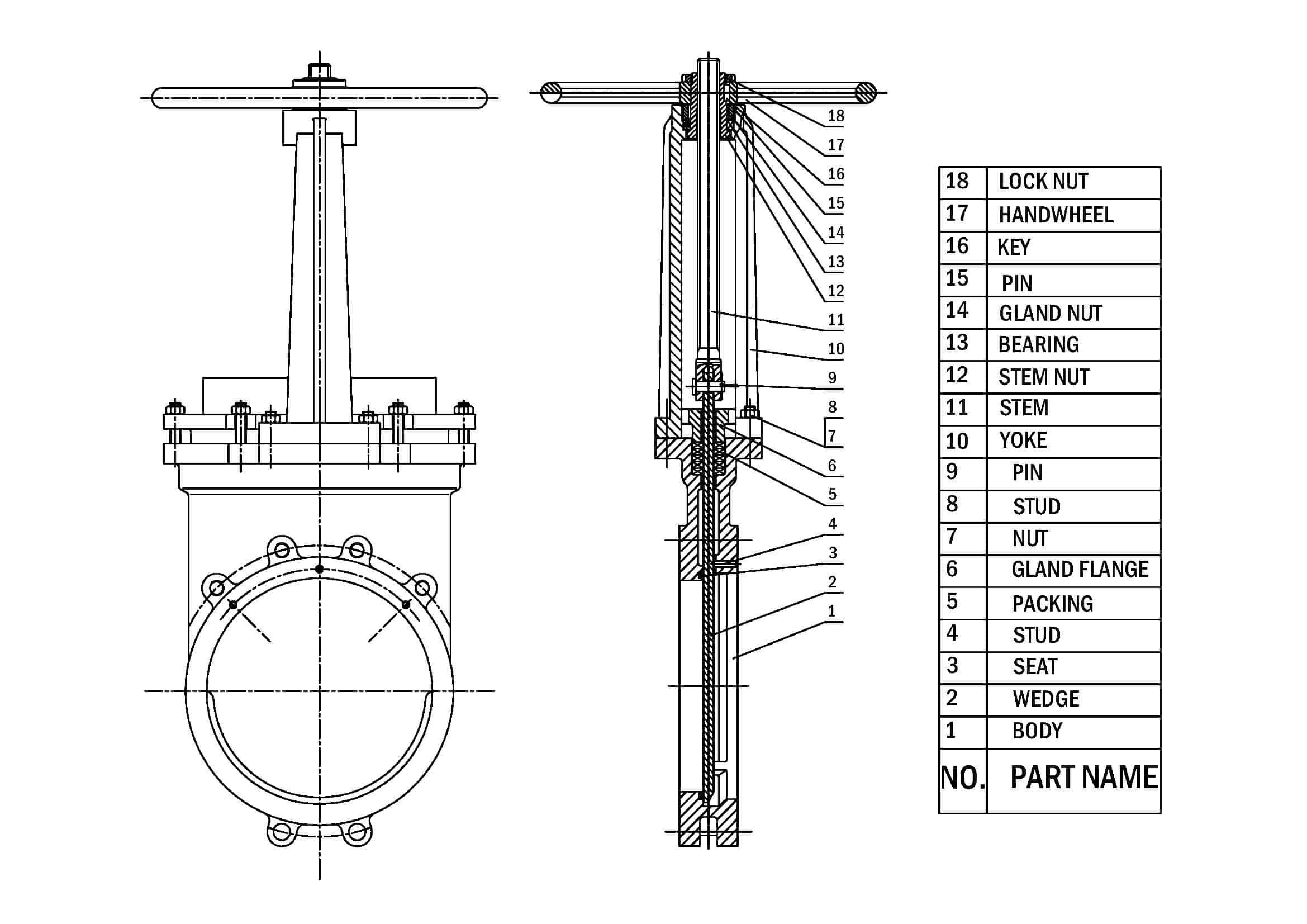
Everything You Need to Know about Knife Gate Valve NTGD valve

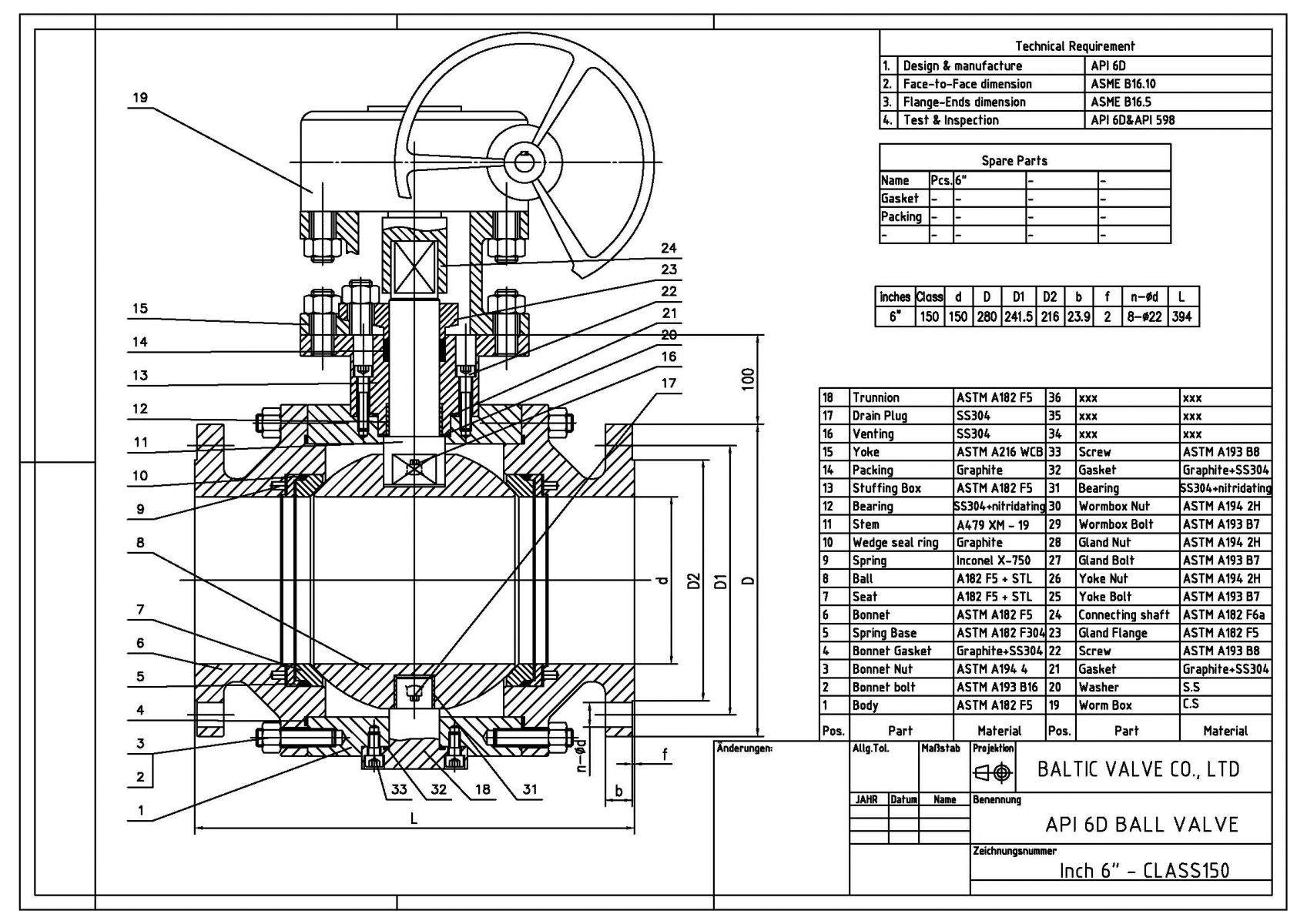
api 6d ball valve dimensions Api 6d metal seated ball valve

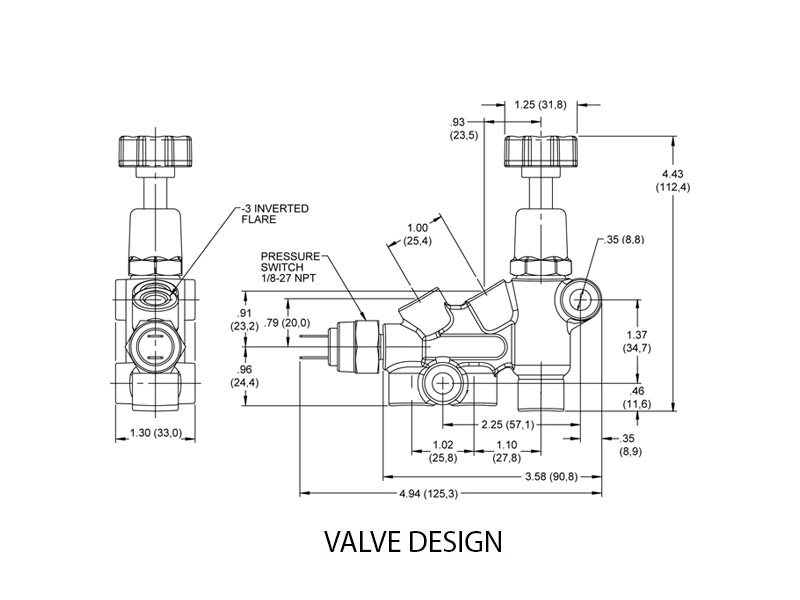
Valve Drawing CAD Pro

ASSEMBLY DRAWING OF CYLINDER RELIEF VALVE YouTube

Valves Manual Valves Globe Valves CTG Technical Blog
The Valves Which Are Mainly Used To Regulate The Flow Of Fluid In Hydraulic Circuits Are Known As “Flow Control Valves”.
Pipes, Tubes And Hoses Are Shown By Using Different Styles Of Lines.
A Comprehensive Guide To Understanding Different Types Is Meticulously Crafted To Serve As An Indispensable Resource For Industry Professionals.
Web We Have A Vast Range Of Experience And Depth Of Expertise In 2D Drafting And 3D Modeling Of Valve Assemblies, Valve Drawing, Actuator Drawing, And Pi&D Diagrams.
Related Post: