Draw Isometric Piping Drawings
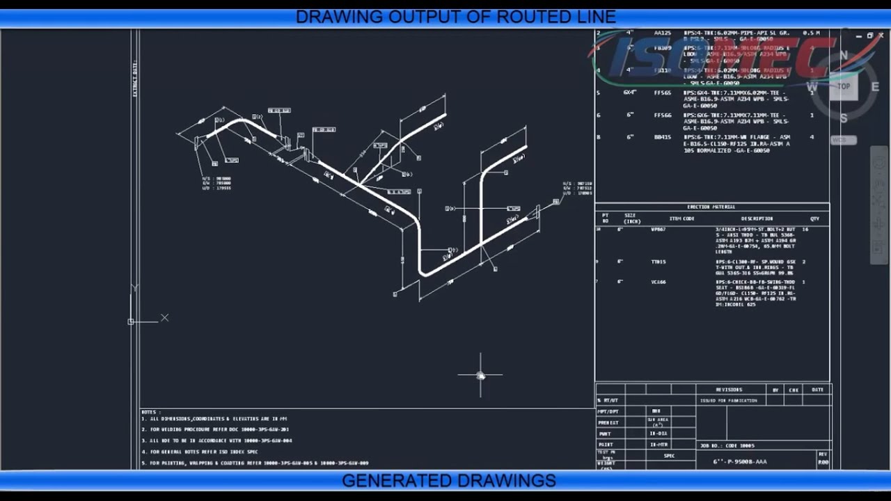
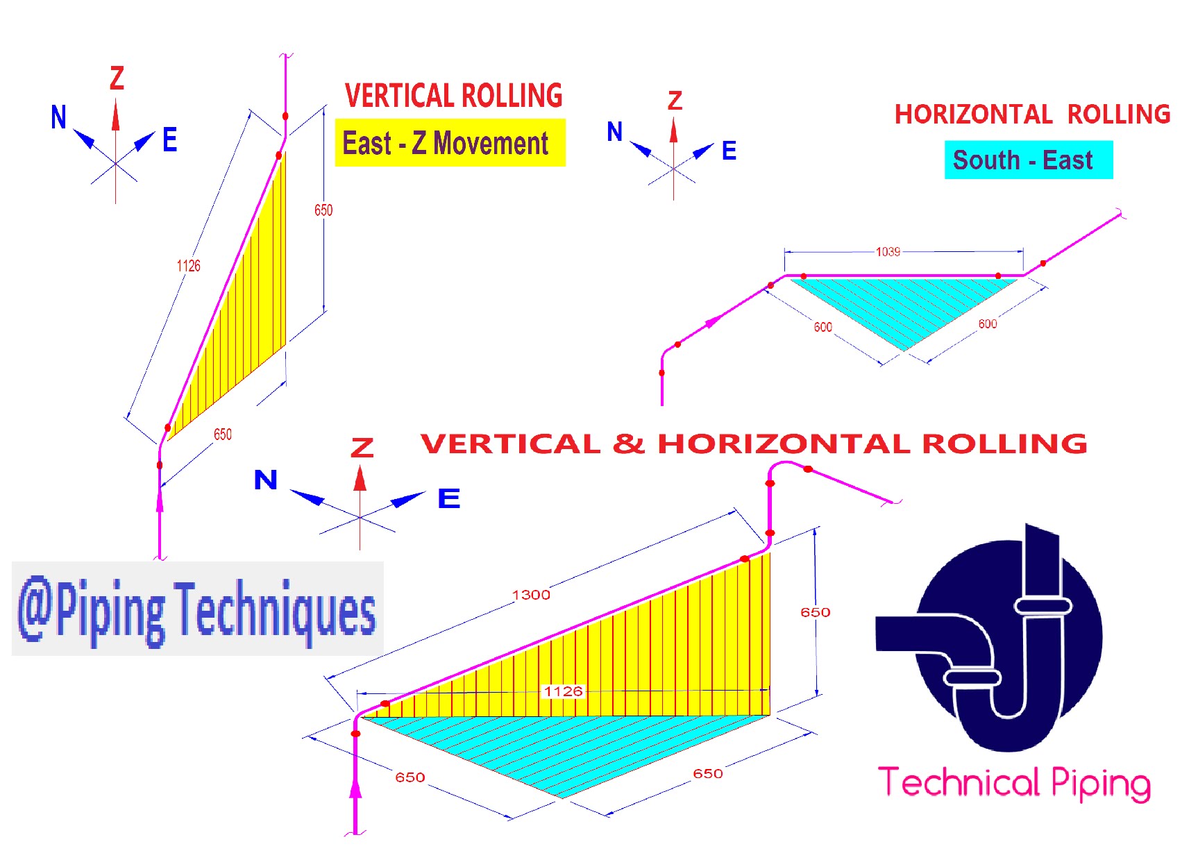
Draw Isometric Piping Drawings - Web how to read piping isometric drawing symbols. Web a piping isometric drawing is a technical drawing that depicts a pipe spool or a complete pipeline using an isometric representation. Piping isometric drawing latest update: So engineers and designers must be aware of the isometric preparation steps. Web the world of isometric drawings in autocad is pretty easy once you know whether you’re talking 2d or 3d. It is not drawn to the scale, but it is proportionate with the exact dimensions represented. Web piping isometric drawing is one of the most important deliverables of the piping discipline as it provides complete information of the piping route to be erected at the construction site. 1) show all major equipment, its north/south and east/west orientation, and all piping leading to and from equipment are developed by piping designers. Isometric drawings are typically used to show the details of a piping system, such as the size and type of piping, the direction of flow of the fluids, and the location of valves, pumps, and other equipment nozzles. Understanding how to read a p&id effectively requires familiarity with standard instrument symbols and standard identification letter codes. It is not drawn to the scale, but it is proportionate with the exact dimensions represented. In other words, each instrument involved in the process appears on the p&id and is represented by a symbol and a code. Piping fabrication work is based on isometric drawings. Unlike orthographic drawings that show different views (front, side, and top) separately, isometric drawings. Piping isometrics are often used by designers prior to a stress analysis and are also used by draftsmen to produce shop fabrication spool drawings. It is the most important deliverable of piping engineering department. Web a piping isometric drawing is a technical illustration that presents a 3d representation of a piping system. Web the purpose in making the piping isometric. It is the most important deliverable of piping engineering department. Web piping isometric drawing is one of the most important deliverables of the piping discipline as it provides complete information of the piping route to be erected at the construction site. Web isometric pipe drawing plays a crucial role in engineering, construction, and design, providing a clear and accurate representation. The drawing axes of the isometrics intersect at an angle of 60°. Web piping isometric drawing is an isometric representation of single pipe line in a plant. Piping fabrication work is based on isometric drawings. Web learn how to draw your own piping isometrics through numerous real industrial examples. Web introduction to isometric reading. Unlike orthographic drawings that show different views (front, side, and top) separately, isometric drawings combine these views into a. Piping isometrics are often used by designers prior to a stress analysis and are also used by draftsmen to produce shop fabrication spool drawings. Web download piping isometric drawing latest version for android free. The drawing axes of the isometrics intersect. These highly structured drawings provide a comprehensive 3d representation of the arrangement, dimensions, and connections of pipes within a system. Piping plan drawings/general arrangement drawings (gad) the piping plan or general arrangement drawings (fig. Web piping isometric drawings are detailed technical illustrations that show a 3d view of piping systems. These tools generate the 3d representation of the piping layout,. Web the purpose in making the piping isometric of a piping configuration is threefold: These highly structured drawings provide a comprehensive 3d representation of the arrangement, dimensions, and connections of pipes within a system. Web piping isometric drawing is an isometric representation of single pipe line in a plant. It is used by the fabricator in fabricating the line. Import. It is used by the fabricator in fabricating the line. Web pipeline isometric drawings explained: Process & instrumentation diagram (p & id) 3. Web introduction to isometric reading. 3 clicks to draw a pipe, 3 clicks to add an elbow, 1 click to add a dimension and 3 clicks to print. Mechanical data sheets (mds) in some of the cases, more detailed piping layout will be available. Sometimes piping isometrics are also known as pipe fitting isometric drawings. Web an isometric drawing is a type of pictorial drawing in which three sides of an object can be seen in one view. Web the world of isometric drawings in autocad is pretty. Web a piping isometric drawing is a technical illustration that presents a 3d representation of a piping system. In other words, each instrument involved in the process appears on the p&id and is represented by a symbol and a code. Web how to read p&id. It is used by the field crew in erecting the line. Isometric drawings are typically. Process & instrumentation diagram (p & id) 3. Sometimes piping isometrics are also known as pipe fitting isometric drawings. Piping isometric is a representation of a single pipe line in a process plant with exact dimensions and bill of material (bom). Piping isometrics are often used by designers prior to a stress analysis and are also used by draftsmen to produce shop fabrication spool drawings. Web the minimum inputs for isometric sketching are: Web isometric pipe drawing plays a crucial role in engineering, construction, and design, providing a clear and accurate representation of complex piping systems. Web piping isometric drawing is one of the most important deliverables of the piping discipline as it provides complete information of the piping route to be erected at the construction site. 3 clicks to draw a pipe, 3 clicks to add an elbow, 1 click to add a dimension and 3 clicks to print. Web pipeline isometric drawings explained: In the world of industrial projects, precision and accuracy are. Import idf or pcf files. Piping fabrication work is based on isometric drawings. Web introduction to isometric reading. Web piping isometric drawing software is an essential tool for piping engineers and designers to create detailed isometric drawings of piping systems. So engineers and designers must be aware of the isometric preparation steps. It’s popular within the process piping industry because it can be laid out and drawn with ease and portrays the.
Piping Isometric Drawing at Explore collection of

Piping Isometric Drawing at Explore collection of

Isometric Pipe Drawing at GetDrawings Free download

Piping Isometric Drawing, Basic piping tutorial YouTube

AUTOCAD TUTORIAL BASIC SETTING DAN DRAWING PIPING ISOMETRIC YouTube

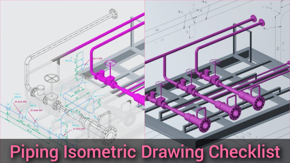
Piping Isometric Drawing Checklist

How to read piping isometric drawing, Pipe fitter training, Watch the

Isometric Piping Drawings Advenser

How to read piping Isometric drawing YouTube

How To Draw Piping Isometric Drawing In Autocad Design Talk
Web Piping Isometric Drawings Are Detailed Technical Illustrations That Show A 3D View Of Piping Systems.
Create Isometric Drawings In Minutes:
It Is Used By The Piping Material Group In Purchasing The Material For The Line.
Web The World Of Isometric Drawings In Autocad Is Pretty Easy Once You Know Whether You’re Talking 2D Or 3D.
Related Post: