Dimensioning In Engineering Drawing
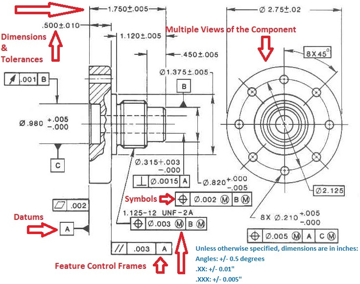
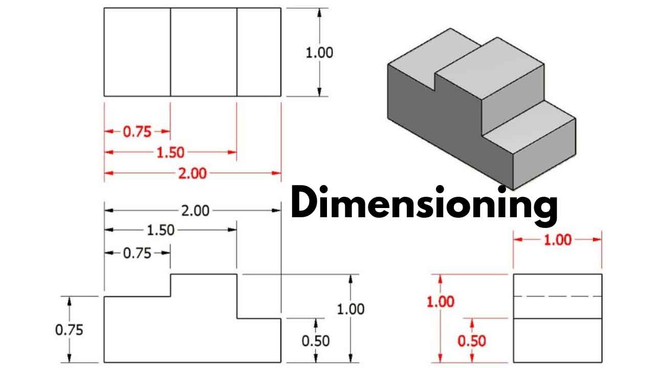
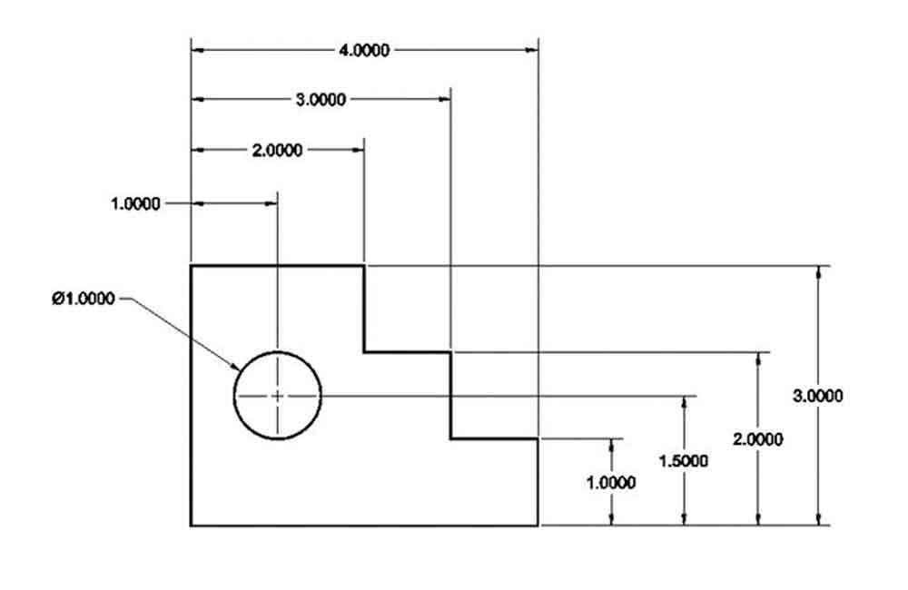
Dimensioning In Engineering Drawing - Web geometric dimensioning and tolerancing is a set of rules and gd&t symbols used on a drawing to communicate the intent of a design, focusing on the function of the part. A common use is to specify the geometry necessary for the construction of a component and is called a detail drawing. They provide measurements that define the length, width, height, or diameter of objects, allowing for accurate replication and manufacturing. Dimensions in engineering drawings are numerical values indicated graphically in a proper unit of measurement on engineering drawing with lines, symbols, and notes. A blank holder is used to prevent wrinkling in the product, especially with thin sheets. Geometrics is the science of specifying and tolerancing the shapes and locations of features on objects. Web an engineering drawing is a type of technical drawing that is used to convey information about an object. After preparing a sketch of any drawing, some information is to be written on it. Usually, a number of drawings are necessary to completely specify even a simple component. Dimensioning should follow these guidelines. A complete set of dimensions will permit only one interpretation needed to construct the part. Standardization of gd&t and knowledge of those standards is crucial to ensure that the design intent is communicated properly. Web in this video, we are going to learn about dimensions in engineering drawing! Web what is dimensioning in engineering drawing? Web the rules that are. Web dimension lines are used to indicate the size and location of features in an engineering drawing. Web on a multiview drawing, dimensions should generally be placed between adjacent views. Dimensions in engineering drawings are numerical values indicated graphically in a proper unit of measurement on engineering drawing with lines, symbols, and notes. Web the purpose of dimensioning is to. The spacing between dimension lines should be uniform throughout the drawing. Web essentially, dimensioning refers to the process of specifying the exact size, shape, and location of different parts and features on an engineering drawing. Dimensions in engineering drawings are numerical values indicated graphically in a proper unit of measurement on engineering drawing with lines, symbols, and notes. For example,. They provide measurements that define the length, width, height, or diameter of objects, allowing for accurate replication and manufacturing. Geometrics is the science of specifying and tolerancing the shapes and locations of features on objects. After preparing a sketch of any drawing, some information is to be written on it. Web as we previously mentioned, we use dimensions to define. Our comprehensive guide covers techniques, standards, and best practices for accuracy and clarity. Rule 1) dimensions should be arranged for maximum readability. Web gd&t, short for geometric dimensioning and tolerancing, is a system for defining and communicating design intent and engineering tolerances that helps engineers and manufacturers optimally control variations in manufacturing processes. Web learn the fundamental rules of dimensioning. Web what is dimensioning in engineering drawing? Geometrics is the science of specifying and tolerancing the shapes and locations of features on objects. Dimensioning should follow these guidelines. Web essentially, dimensioning refers to the process of specifying the exact size, shape, and location of different parts and features on an engineering drawing. Web learn the fundamental rules of dimensioning in. Learning and understanding of how dimensions are mentioned are very easy if you focus on learning. Web deep drawing is the process of drawing sheet metal blank into a desired shape. The spacing between dimension lines should be uniform throughout the drawing. Using gd&t results in a more accurate design, larger tolerances for less important design features, and cost savings. They provide measurements that define the length, width, height, or diameter of objects, allowing for accurate replication and manufacturing. Web geometric dimensioning and tolerancing is a set of rules and gd&t symbols used on a drawing to communicate the intent of a design, focusing on the function of the part. Our comprehensive guide covers techniques, standards, and best practices for. Web an engineering drawing is a type of technical drawing that is used to convey information about an object. A common use is to specify the geometry necessary for the construction of a component and is called a detail drawing. Web what is dimensioning? Web geometric dimensioning and tolerancing is used to communicate detailed information on technical drawings. Web engineering. Dimensions in engineering drawings are numerical values indicated graphically in a proper unit of measurement on engineering drawing with lines, symbols, and notes. Web the process of adding size information to a drawing is known as dimensioning the drawing. Learning and understanding of how dimensions are mentioned are very easy if you focus on learning. Standardization of gd&t and knowledge. Web what is dimensioning? The spacing between dimension lines should be uniform throughout the drawing. Web gd&t, short for geometric dimensioning and tolerancing, is a system for defining and communicating design intent and engineering tolerances that helps engineers and manufacturers optimally control variations in manufacturing processes. Dimensions must be placed in appropriate positions. Geometrics is the science of specifying and tolerancing the shapes and locations of features on objects. Web the purpose of dimensioning is to provide a clear and complete description of an object. They provide measurements that define the length, width, height, or diameter of objects, allowing for accurate replication and manufacturing. Learning and understanding of how dimensions are mentioned are very easy if you focus on learning. Dimensions should be placed in the most descriptive view of the feature. Web the process of adding size information to a drawing is known as dimensioning the drawing. After preparing a sketch of any drawing, some information is to be written on it. Avoid dimensioning to a hidden line and avoid the duplication of dimensions. Once the shape of a part is defined with an orthographic drawings, the size information is added also in the form of dimensions. Usually, a number of drawings are necessary to completely specify even a simple component. A dimension is a numerical value that expresses the size, location, orientation, form, or any other geometric properties of a component in the appropriate units of measurement. Web geometric dimensioning and tolerancing (gd&t) is a system of symbols and standards used in engineering drawings and models to specify the required form, size, orientation, and location of parts and features.
GENERAL RULES OF DIMENSIONING in Engineering Drawing YouTube

SOLUTION Dimensioning in engineering drawing Studypool

Technical Drawing Dimensions Design Talk

Types Of Dimensions In Engineering Drawing at GetDrawings Free download

Types Of Dimensions In Engineering Drawing at GetDrawings Free download

METHOD OF DIMENSIONING ALIGNED METHOD II Engineering drawing II YouTube

Types Of Dimensions In Engineering Drawing at GetDrawings Free download

Dimensioning Drafting Drawings

Dimensioning and its role in drafting and design

Example of an industrial drawing with dimensioning and tolerancing
Web An Engineering Drawing Is A Type Of Technical Drawing That Is Used To Convey Information About An Object.
Our Comprehensive Guide Covers Techniques, Standards, And Best Practices For Accuracy And Clarity.
Web As We Previously Mentioned, We Use Dimensions To Define The Size And Shape Of An Engineering Component.
Correct Values Must Be Given.
Related Post: