Buck Converter Design
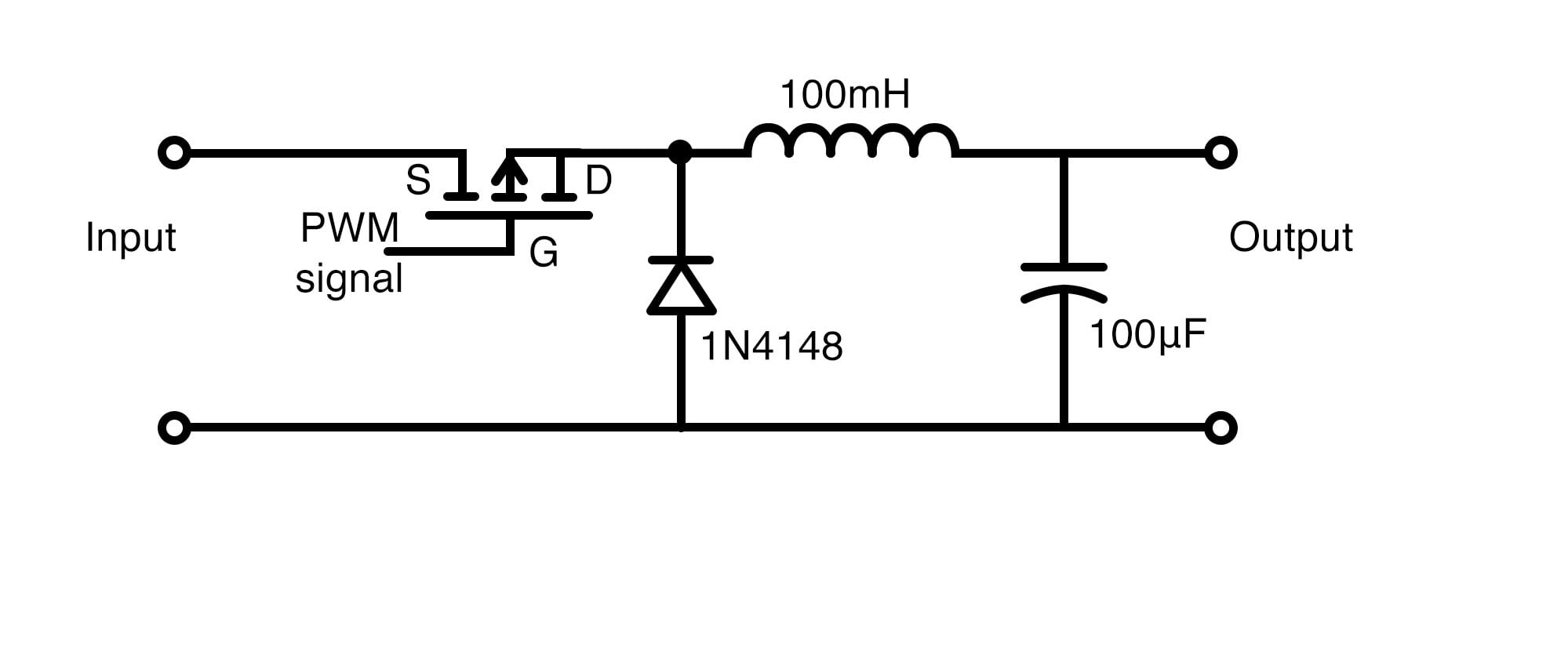
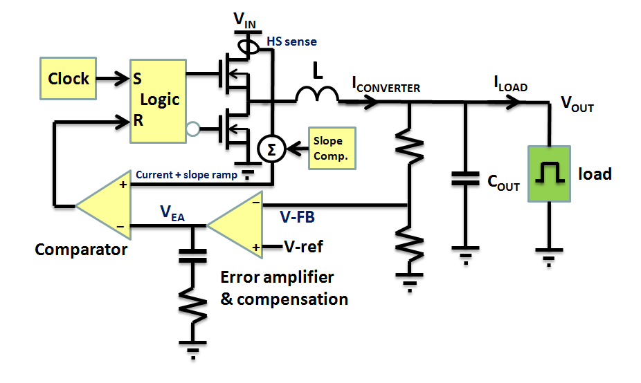
Buck Converter Design - Learn how inductors, capacitors, and feedback loops work together to regulate power efficiently. Dc = v out /v in. Web buck converter design tutorial. Design of buck converter for 12v to 2.5v 1a. Web in buck converters, the flow of current through the inductor can be described by two distinct conduction modes: Ti suggests carrying out the design at the highest output power level (which is the highest output resistance) using either webench® designer or the lm5117 quick start calculator. They can convert a voltage source (typically 8 v to 25 v) into a lower regulated voltage (typically 0.5 v to 5 v). Web this application report gives the formulas to calculate the power stage of a buck converter built with an integrated circuit having a integrated switch and operating in continuous conduction mode. Server motherboards, broadband communication boards, etc. The duty cycle of the converter is given by: Web designing a buck converter. Web operation and design principles of buck converters explained. Continuous conduction mode (ccm) and discontinuous conduction mode (dcm). Web stepdown (buck) switching converters are integral to modern electronics. Design of buck converter for 12v to 2.5v 1a. Web buck converter design tutorial. Determine the input voltage and the output voltage and current. Ti suggests carrying out the design at the highest output power level (which is the highest output resistance) using either webench® designer or the lm5117 quick start calculator. Determine the output power, that is, the product of. Learn how inductors, capacitors, and feedback loops work. Web this application report gives the formulas to calculate the power stage of a buck converter built with an integrated circuit having a integrated switch and operating in continuous conduction mode. Web buck converter design tutorial. Web in buck converters, the flow of current through the inductor can be described by two distinct conduction modes: Design of buck converter for. Web designing a buck converter. It is not intended to give details on the functionality of a buck converter or how to compensate a converter. Web buck converter design tutorial. Types, circuit design, modes of operation, examples, losses and applications. Ti suggests carrying out the design at the highest output power level (which is the highest output resistance) using either. Web designing a buck converter. Dc = v out /v in. It is not intended to give details on the functionality of a buck converter or how to compensate a converter. The duty cycle of the converter is given by: Continuous conduction mode (ccm) and discontinuous conduction mode (dcm). Complete analysis with calculations and sample design. Continuous conduction mode (ccm) and discontinuous conduction mode (dcm). Types, circuit design, modes of operation, examples, losses and applications. It is not intended to give details on the functionality of a buck converter or how to compensate a converter. Server motherboards, broadband communication boards, etc. Understanding these modes is essential for. Web buck converter design tutorial. Web stepdown (buck) switching converters are integral to modern electronics. Web designing a buck converter. It is not intended to give details on the functionality of a buck converter or how to compensate a converter. Continuous conduction mode (ccm) and discontinuous conduction mode (dcm). Web stepdown (buck) switching converters are integral to modern electronics. Ti suggests carrying out the design at the highest output power level (which is the highest output resistance) using either webench® designer or the lm5117 quick start calculator. Dc = v out /v in. Web see the different types of buck. It is not intended to give details on the functionality of a buck converter or how to compensate a converter. They can convert a voltage source (typically 8 v to 25 v) into a lower regulated voltage (typically 0.5 v to 5 v). The duty cycle of the converter is given by: Continuous conduction mode (ccm) and discontinuous conduction mode. Understanding these modes is essential for. Web designing a buck converter. Continuous conduction mode (ccm) and discontinuous conduction mode (dcm). Complete analysis with calculations and sample design. Types, circuit design, modes of operation, examples, losses and applications. Types, circuit design, modes of operation, examples, losses and applications. Web see the different types of buck converters used in dc to dc buck conversion, along with comparisons diagrams of the various control techniques for these converters. Server motherboards, broadband communication boards, etc. Understanding these modes is essential for. Complete analysis with calculations and sample design. Continuous conduction mode (ccm) and discontinuous conduction mode (dcm). The duty cycle of the converter is given by: Web in buck converters, the flow of current through the inductor can be described by two distinct conduction modes: Design of buck converter for 12v to 2.5v 1a. Determine the output power, that is, the product of. Ti suggests carrying out the design at the highest output power level (which is the highest output resistance) using either webench® designer or the lm5117 quick start calculator. Learn how inductors, capacitors, and feedback loops work together to regulate power efficiently. Web this application report gives the formulas to calculate the power stage of a buck converter built with an integrated circuit having a integrated switch and operating in continuous conduction mode. It is not intended to give details on the functionality of a buck converter or how to compensate a converter. Web designing a buck converter. Web a basic buck converter.
LTSpice Buck converter Design Simulation YouTube

How to Build an Arduinobased Buck/Boost Converter Arduino Maker Pro

BUCK CONVERTER DESIGN FORMULAE AND SIMULATION USING PSIM SOFTWARE YouTube

Buck Converter Design Tutorial Complete Equation Derivation and

Design of Buck Converter

Stepdown buck converter DCDC 300w Ben's electronics

Buck Converter Design and Simulation YouTube

Comparing Buck Converter Topologies Richtek Technology

Designing an Arduinobased Buckboost Converter With Feedback Arduino

Converter Evaluation and Design Technical Articles
Web Buck Converter Design Tutorial.
They Can Convert A Voltage Source (Typically 8 V To 25 V) Into A Lower Regulated Voltage (Typically 0.5 V To 5 V).
Dc = V Out /V In.
Web Stepdown (Buck) Switching Converters Are Integral To Modern Electronics.
Related Post: