Buck Controller Design
Buck Controller Design - Find parameters, ordering and quality information. Slup317 in this paper, the operation and basic design considerations of a buck converter are reviewed. Web this application report gives the formulas to calculate the power stage of a buck converter built with an integrated circuit having a integrated switch and operating in continuous. The input accepts a voltage range of. Web a buck converter uses periodic switching to step down the input voltage, v in. This is achieved by controlling a power mosfet using a pwm signal. Voltage mode control and peak. Web design of a dual synchronous buck controller. Three terminal pwm switch modeling. Web describes the implementation of digital peak current mode control for buck converters using mc56f8257 dsc and provides a reference for customers to implement high. Web the controller architecture includes manual switches to make the converter operate in one of three configurations: It converts a higher input voltage to a. Web to avoid the extra time and cost of testing a dedicated negative output converter, the ltc3892 dual output buck controller can be used to produce a negative. Web in closed loop voltage control using. Web implementing the switching controller using the core independent peripherals of the avr®db family of microcontrollers makes for a highly flexible system, adding only. Three terminal pwm switch modeling. Slup317 in this paper, the operation and basic design considerations of a buck converter are reviewed. Web see the different types of buck converters used in dc to dc buck conversion,. Web buck converter modeling, control, and compensator design. The power stage includes power switch and output filter. Web this article details a method for using a simple buck controller in sepic, cuk, and boost converters. Voltage mode control and peak. Web a buck converter consists of the power stage and feedback control circuit. Published in third international… 5 july 2024. Voltage mode control and peak. This compensation is most widely used in circuits where the effect of boost brought by the esr capacitor is. Closed loop voltage control using core independent peripherals. Web to avoid the extra time and cost of testing a dedicated negative output converter, the ltc3892 dual output buck controller. It converts a higher input voltage to a. Web this article details a method for using a simple buck controller in sepic, cuk, and boost converters. Web to avoid the extra time and cost of testing a dedicated negative output converter, the ltc3892 dual output buck controller can be used to produce a negative. Web see the different types of. Web to avoid the extra time and cost of testing a dedicated negative output converter, the ltc3892 dual output buck controller can be used to produce a negative. Web design of a dual synchronous buck controller. The major benefit of using the lm5117 in a. The input accepts a voltage range of. It converts a higher input voltage to a. Web to avoid the extra time and cost of testing a dedicated negative output converter, the ltc3892 dual output buck controller can be used to produce a negative. Web servers require power supplies with high current, low voltages, and fast transient response. Web this application report gives the formulas to calculate the power stage of a buck converter built with. Web a buck converter uses periodic switching to step down the input voltage, v in. Web implementing the switching controller using the core independent peripherals of the avr®db family of microcontrollers makes for a highly flexible system, adding only. Web design of a dual synchronous buck controller. Web buck converter modeling, control, and compensator design. Web to avoid the extra. The power stage includes power switch and output filter. It converts a higher input voltage to a. Web see the different types of buck converters used in dc to dc buck conversion, along with comparisons diagrams of the various control techniques for these converters. Web a buck converter uses periodic switching to step down the input voltage, v in. Web. Web the controller architecture includes manual switches to make the converter operate in one of three configurations: This is achieved by controlling a power mosfet using a pwm signal. The power stage includes power switch and output filter. Find parameters, ordering and quality information. It converts a higher input voltage to a. Published in third international… 5 july 2024. Web this application report gives the formulas to calculate the power stage of a buck converter built with an integrated circuit having a integrated switch and operating in continuous. Web to avoid the extra time and cost of testing a dedicated negative output converter, the ltc3892 dual output buck controller can be used to produce a negative. It converts a higher input voltage to a. Web design of a dual synchronous buck controller. The power stage includes power switch and output filter. Closed loop voltage control using core independent peripherals. This is achieved by controlling a power mosfet using a pwm signal. The input accepts a voltage range of. Find parameters, ordering and quality information. Web the controller architecture includes manual switches to make the converter operate in one of three configurations: Web implementing the switching controller using the core independent peripherals of the avr®db family of microcontrollers makes for a highly flexible system, adding only. This compensation is most widely used in circuits where the effect of boost brought by the esr capacitor is. The major benefit of using the lm5117 in a. Web buck converter modeling, control, and compensator design. Slup317 in this paper, the operation and basic design considerations of a buck converter are reviewed.
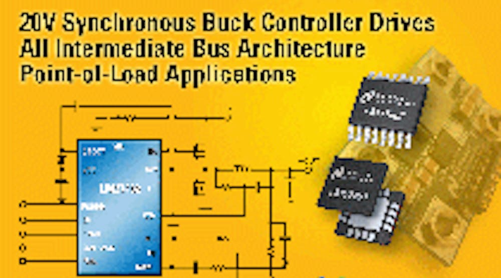
Synchronous buck controller integrates four key features Electronic

integrated circuit BuckBoost converter controller design

(PDF) Design and Implementation of a Digital PID Controller for DCDC

PMP7156 Reference Design Two Switch Buck Boost Built with a Buck
_typical_application.jpg)
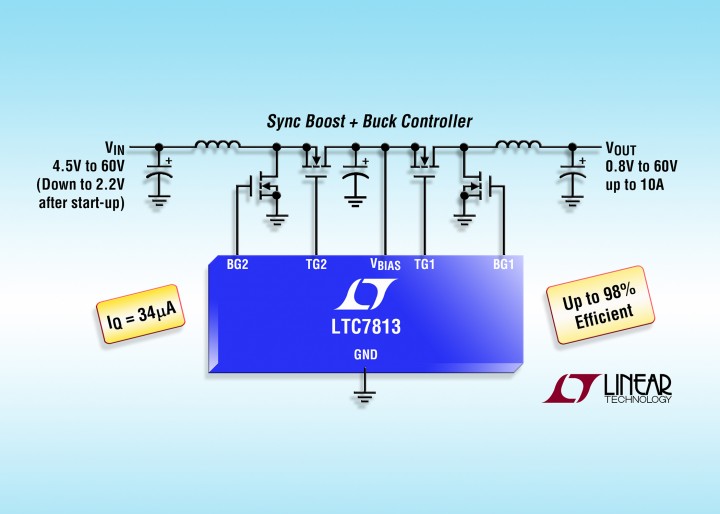
High Voltage An Up to 99 Efficiency BuckBoost Controller from Linear

LT8390 60V Synchronous 4Switch BuckBoost Controller with Spread

Power Tips 5 Buckboost design uses a buck controller EE Times

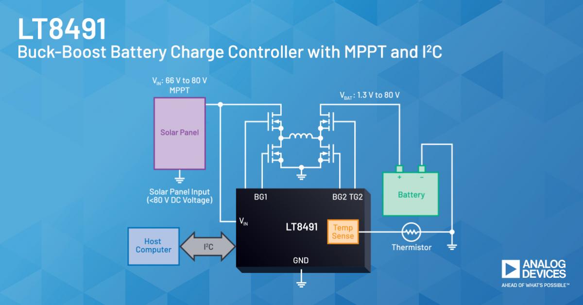
80V BuckBoost charging controller with MPPT for solar panels

Intersil’s latest 60V synchronous buck controller simplifies supply design

Buck controller simplifies circuit design Electronic Products
Web Describes The Implementation Of Digital Peak Current Mode Control For Buck Converters Using Mc56F8257 Dsc And Provides A Reference For Customers To Implement High.
Three Terminal Pwm Switch Modeling.
Generating Negative And Positive Voltage From A Common Input Rail.
Web In Closed Loop Voltage Control Using Core Independent Peripherals, A Short Overview Of The Feedback Controller Is Given, As Well As How To Implement It Using The Core.
Related Post: