Ansi Tolerance Chart
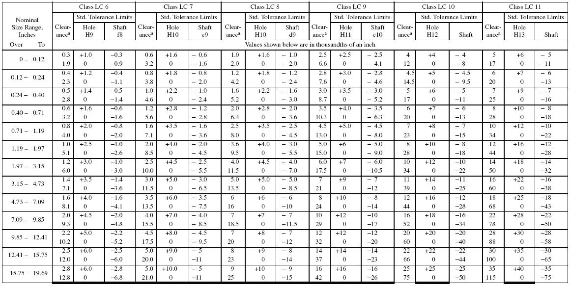
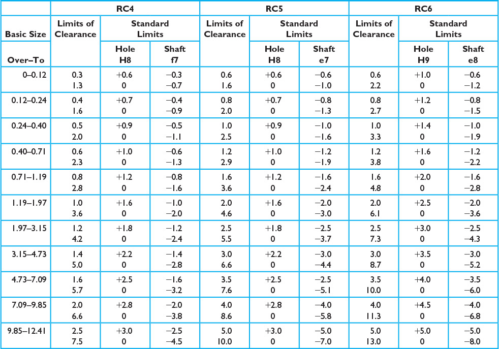
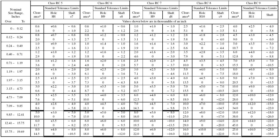
Ansi Tolerance Chart - The first provides the charts for the fundamental deviations (g, j, etc.) and tolerance grades (7, 8, 9, etc.), out of which the limits of the tolerance classes (h7, g6, etc.) can be calculated. The difference between the segment dimensions (width, depth, and intermediate depth) in the mounted pair shall not exceed 0.5mm unless specified. 1 in (inch) = 25.4 mm Ansi b4.1 tolerance table provides a suitable range from which appropriate tolerance for holes and shaft can be selected. According to nominal size and fit type selection among running and sliding [rc], locational clearance [lc], locational transition [lt], locational interference [ln], force and shrink [fn] fits, size limits for hole/shaft are calculated with. Web ansi b4.1 standard tolerances are indicated in the diagram below: The ansi b4.1 tolerance charts are provided in thousandths (.001) of an inch. Web segment size & tilt tolerance for multifocals. Web ansi limits and fits calculator works in line with ansi b4.1 standard which is based on inch units. Running and sliding fits [rc]: Web ansi b4.1 system of tolerances is prescribed by the standard for basic sizes up to 200 in. Web this standard defines preferred tolerances for limits and fits for nonthreaded cylindrical features and defines specific sizes, fits, tolerances, and allowances for use where they are applicable. Running and sliding fits [rc]: According to nominal size and fit type selection among. Web preferred tolerances and fits charts according to ansi b4.1 standard. Web ansi b4.1 standard tolerances are indicated in the diagram below: Ansi b4.1 tolerance table provides a suitable range from which appropriate tolerance for holes and shaft can be selected. The difference between the segment dimensions (width, depth, and intermediate depth) in the mounted pair shall not exceed 0.5mm. The first provides the charts for the fundamental deviations (g, j, etc.) and tolerance grades (7, 8, 9, etc.), out of which the limits of the tolerance classes (h7, g6, etc.) can be calculated. Web ansi b4.1 standard tolerances are indicated in the diagram below: 1 in (inch) = 25.4 mm Running and sliding fits [rc]: The segment dimensions (width,. Web ansi b4.1 system of tolerances is prescribed by the standard for basic sizes up to 200 in. Ansi b4.1 tolerance table provides a suitable range from which appropriate tolerance for holes and shaft can be selected. The segment dimensions (width, depth, and intermediate depth) shall not deviate from the nominal value by more than ± 0.5mm. Web this standard. The difference between the segment dimensions (width, depth, and intermediate depth) in the mounted pair shall not exceed 0.5mm unless specified. Web ansi b4.1 system of tolerances is prescribed by the standard for basic sizes up to 200 in. Ansi b4.1 tolerance table provides a suitable range from which appropriate tolerance for holes and shaft can be selected. According to. According to nominal size and fit type selection among running and sliding [rc], locational clearance [lc], locational transition [lt], locational interference [ln], force and shrink [fn] fits, size limits for hole/shaft are calculated with. The first provides the charts for the fundamental deviations (g, j, etc.) and tolerance grades (7, 8, 9, etc.), out of which the limits of the. Ansi b4.1 tolerance table provides a suitable range from which appropriate tolerance for holes and shaft can be selected. The segment dimensions (width, depth, and intermediate depth) shall not deviate from the nominal value by more than ± 0.5mm. The ansi b4.1 tolerance charts are provided in thousandths (.001) of an inch. Running and sliding fits [rc]: The difference between. The difference between the segment dimensions (width, depth, and intermediate depth) in the mounted pair shall not exceed 0.5mm unless specified. Web this calculator will determine the gage class and tolerance per ansi asme b89.1.5 for cylindrical i.d and o.d. Ansi b4.1 tolerance table provides a suitable range from which appropriate tolerance for holes and shaft can be selected. Intended. Intended to provide a similar running performance, with suitable lubrication allowance, through out the range of sizes. Web preferred tolerances and fits charts according to ansi b4.1 standard. Ansi b4.1 tolerance table provides a suitable range from which appropriate tolerance for holes and shaft can be selected. The segment dimensions (width, depth, and intermediate depth) shall not deviate from the. Web this standard defines preferred tolerances for limits and fits for nonthreaded cylindrical features and defines specific sizes, fits, tolerances, and allowances for use where they are applicable. Web ansi b4.1 standard tolerances are indicated in the diagram below: Intended to provide a similar running performance, with suitable lubrication allowance, through out the range of sizes. Web ansi b4.1 system. Running and sliding fits [rc]: The segment dimensions (width, depth, and intermediate depth) shall not deviate from the nominal value by more than ± 0.5mm. Web segment size & tilt tolerance for multifocals. Web ansi b4.1 standard tolerances are indicated in the diagram below: The difference between the segment dimensions (width, depth, and intermediate depth) in the mounted pair shall not exceed 0.5mm unless specified. According to nominal size and fit type selection among running and sliding [rc], locational clearance [lc], locational transition [lt], locational interference [ln], force and shrink [fn] fits, size limits for hole/shaft are calculated with. Web ansi limits and fits calculator works in line with ansi b4.1 standard which is based on inch units. Web this standard defines preferred tolerances for limits and fits for nonthreaded cylindrical features and defines specific sizes, fits, tolerances, and allowances for use where they are applicable. Web ansi b4.1 system of tolerances is prescribed by the standard for basic sizes up to 200 in. The first provides the charts for the fundamental deviations (g, j, etc.) and tolerance grades (7, 8, 9, etc.), out of which the limits of the tolerance classes (h7, g6, etc.) can be calculated. 1 in (inch) = 25.4 mm The ansi b4.1 tolerance charts are provided in thousandths (.001) of an inch.
ANSI Tolerance Chart
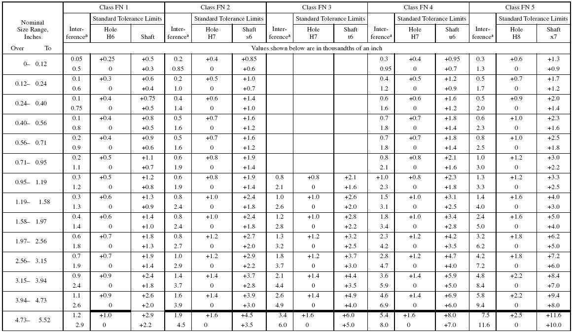
American National Standard Runni
ISO 286/ANSI B4.21978 International Tolerance Grade PDF
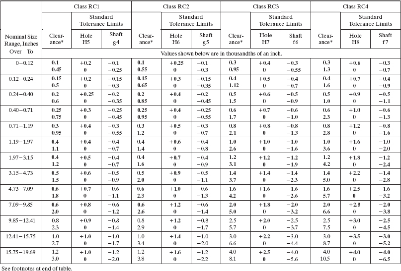
APPENDIX A ANSI PREFERRED ENGLISH LIMITS AND FITS Engineering Design

Geometric Tolerancing Reference Chart ANSI/AMSE … Guide Charts
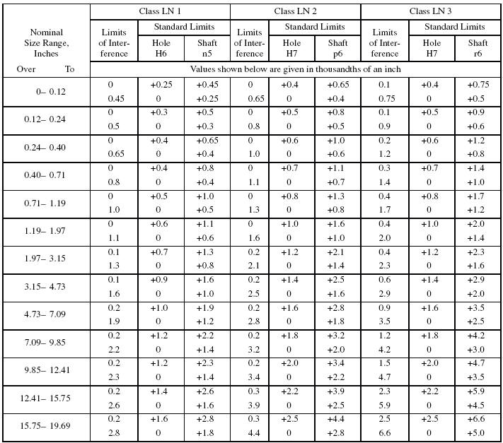
American National Standard Runni
American National Standard Runni

American National Standard Runni
Appendix A. ANSI and ISO Tolerance Tables Mastering SolidWorks® The
American National Standard Runni
Web This Calculator Will Determine The Gage Class And Tolerance Per Ansi Asme B89.1.5 For Cylindrical I.d And O.d.
Intended To Provide A Similar Running Performance, With Suitable Lubrication Allowance, Through Out The Range Of Sizes.
Web Preferred Tolerances And Fits Charts According To Ansi B4.1 Standard.
Ansi B4.1 Tolerance Table Provides A Suitable Range From Which Appropriate Tolerance For Holes And Shaft Can Be Selected.
Related Post:
